Content last revised on September 20, 2026
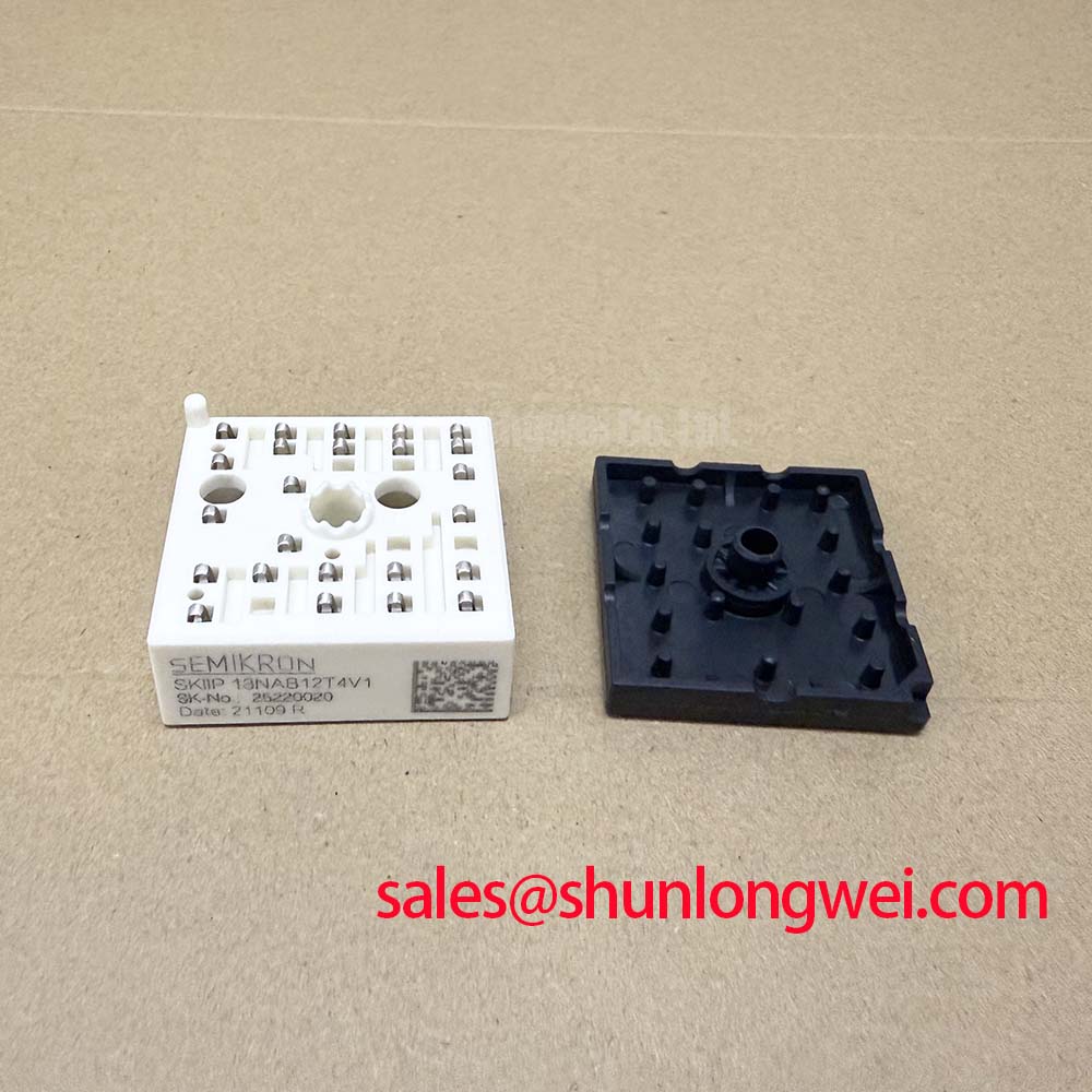
Assembly Integrity & Layout Architecture: Implementing Suppression of 2× VDC Voltage Doubling for SKIIP 13NAB12T4V1
Long motor cables can behave as transmission lines rather than simple conductors. During fast inverter switching, a steep voltage transition launched from the power module can reflect from the motor-end impedance mismatch. Under unfavorable cable length, motor impedance, grounding, and switching-edge conditions, the motor terminal can experience a reflected waveform approaching twice the DC-link voltage. This is a system-level phenomenon, so it must not be confused with the 1200 V collector-emitter rating of the SKIIP 13NAB12T4V1.
When servicing a servo drive with repeated motor insulation alarms, unexplained overvoltage trips, or failures appearing only with a remote actuator connected, inspect the motor cable and output filter arrangement before condemning the power module. A short local motor lead may operate normally while a long routed cable produces a materially different waveform. Engineers should measure phase-to-phase and phase-to-protective-earth waveforms using appropriate high-voltage differential measurement equipment, then compare the result with the drive manufacturer’s permitted switching and motor-insulation limits.
Design Consideration: An output reactor or dv/dt filter can reduce the rate and amplitude of reflected motor-terminal transients when cable behavior is confirmed as a contributing factor. The component selection depends on the inverter switching characteristics, cable construction, motor insulation system, allowable voltage drop, control-loop requirements, and measured waveform. The system engineer should validate the completed filter arrangement on the actual motor and cable route rather than applying a generic inductance or capacitance value.
At the module side, keep the DC-link capacitor connection physically close to the inverter power path where the original equipment layout allows. Long bus structures, shared return paths, and poor bonding can add parasitic inductance that increases overshoot during commutation. Inspect laminated busbars, capacitor lugs, terminal hardware, and cable crimp condition. A corroded or loosened DC-link connection can alter both electrical impedance and thermal behavior, making a transient problem appear as a module defect.
Metal enclosure clearances, cable separation, and protective-earth bonding should follow the original equipment design and applicable system safety requirements. There is no basis to assign a universal clearance value to this module without the complete insulation coordination, contamination environment, working voltage, and enclosure construction. If a MOV is present across the DC link, inspect it as part of the coordinated surge-control network. A MOV is intended to clamp transient energy under defined conditions, but its condition, coordination with capacitors, and suitability for the actual transient must be assessed at system level.
For platform comparison, the SKIIP37AC12T4V1 should be reviewed only against the original drive’s electrical schematic, mechanical footprint, gate-drive interface, thermal assembly, and protection architecture. Matching a voltage class alone does not establish interchangeability.
SKIIP 13NAB12T4V1 Operational Boundaries: Evaluating Thermal Capacitance Versus Heatsink Limits
The 330 W per IGBT power-dissipation figure is specified at Tcase = 25 °C. It does not mean that every installed servo drive can continuously remove that amount of heat. In a working actuator cabinet, the actual case temperature is affected by heatsink capacity, fan operation, airflow direction, enclosure temperature, dust loading, thermal interface condition, mounting pressure, and the duty cycle of acceleration, holding, regeneration, and deceleration.
Heavy pulsed loading requires transient thermal evaluation rather than a simple steady-state calculation. Engineering Calculation may use the manufacturer’s transient thermal-impedance model, commonly represented through multiple thermal RC sections, to estimate junction-temperature movement during a pulse train. The heat generated during conduction is influenced by current and the stated VCE(sat); switching energy and real gate-drive behavior also contribute. The resulting estimated peak junction temperature must remain within the official −40 °C to +150 °C operating-junction-temperature range after the system’s actual case temperature and pulse profile are included.
A service technician can often identify poor heat transfer without inventing a failure cause. Remove power, allow the assembly to cool, then inspect whether the module base and heatsink show a complete and even thermal-contact imprint. Uneven compound displacement, debris, burrs, warped surfaces, or a diagonal fastening pattern can create localized temperature rise. Rebuild the thermal interface using the equipment manufacturer’s approved material and mechanical process.
Design Consideration: A thin, uniform thermal interface layer is generally used to fill microscopic surface variation without creating an unnecessarily thick thermal barrier. A 50–80 µm thermal-interface thickness is a general industry reference range, not an official SKIIP 13NAB12T4V1 factory mounting requirement. The applicable material, thickness, screw type, torque, and insulation arrangement must be taken from the original drive mechanical documentation.
⚠️ Field Alert: Tighten heatsink fasteners in a cross-pattern sequence to the equipment manufacturer’s specified torque, because uneven clamping can damage the interface or distort the module seating surface.
For drives used in bidirectional DC-DC battery charging or regenerative servo systems, thermal cycling may be more relevant than the average output current. Repeated transitions between motoring and regeneration can move power loss among switching devices and the braking path. Check fan response, heatsink cleanliness, thermal sensors, and logged DC-link events while reproducing the actual motion profile. A stable bench load may not reproduce the rapid current reversals that occur during real positioning cycles.
The Semikron MiniSKiiP® power module information provides useful product-family context, but the original module documentation and host-drive design remain the controlling references for service integration.
Assembly Integrity & Layout Architecture: Mitigating Hard Switching Transients for SKIIP 13NAB12T4V1
A gate-drive protection circuit must react before the module exceeds its published short-circuit capability. The official SKIIP 13NAB12T4V1 short-circuit withstand specification is at least 10 µs only under its stated test conditions. In a practical motor controller, desaturation detection, current sensing, fault logic propagation, and gate discharge all consume time. The protection path therefore requires validation as a complete sequence, including the real DC-link voltage, junction temperature, gate-drive supply condition, and stray inductance in the commutation path.
Type I short-circuit behavior can occur when a commanded device turns on into a faulted load condition. Type II behavior can occur when a fault develops while the device is already conducting. These cases can create different current-rise and voltage conditions, so a controller that recognizes one event adequately may still require review under the other. During repair, inspect the fault-record history where available, then verify the current sensor, desaturation circuit, comparator threshold network, isolated drive supply, and shutdown command path against a known-good channel or manufacturer reference.
Design Consideration: Two-stage soft turn-off is commonly used in protected IGBT drive circuits to avoid an excessively abrupt current interruption after a detected short circuit. The principle is to reduce turn-off speed in the fault event sufficiently to limit inductive overvoltage, while still removing gate drive quickly enough to protect the semiconductor. The actual gate resistance, gate-voltage levels, delay, and clamping arrangement are system-determined and must be verified with switching measurements.
Hard switching oscillation is often visible as ringing on collector-emitter voltage, gate-emitter voltage, or DC-link current. It may result from the combined interaction of gate-loop inductance, DC-link layout, capacitor placement, probe technique, and load wiring. Before changing drive components, verify the measurement setup. A long oscilloscope ground lead can create misleading ringing that is absent from the real switching node. Use an appropriate differential or isolated measurement method and compare with a known-good phase where possible.
Keep the gate-drive return path controlled and avoid unnecessary loop area between the driver and the associated module control terminals. This is an Engineering Recommendation intended to suppress unwanted gate-voltage disturbance during high di/dt switching. The required damping and protection configuration depend on the host drive. For background on a commonly evaluated turn-off approach, see Evolution of Negative Off-Bias Gate Drive Circuits.
The manufacturer’s SKiiP® technology information is relevant for understanding the broader technology platform, but it does not replace a waveform check at the terminals of the particular controller being repaired.
Transient Dynamics & Electrical Design: Sizing Braking Resistors and Chopper Transients for SKIIP 13NAB12T4V1
During rapid deceleration, a BLDC or stepper servo actuator can return mechanical energy to the DC link. If the upstream supply cannot absorb that energy, the DC-link voltage rises until the controller’s regenerative-energy path acts or an overvoltage shutdown occurs. The SKIIP 13NAB12T4V1 is rated at 1200 V VCES, but that rating must not be treated as a braking threshold. The actual DC-link operating limit is determined by the drive’s capacitor ratings, control strategy, protection settings, motor speed, and braking circuitry.
Start by identifying whether the original controller uses an integrated chopper arrangement, an external braking transistor, a separate braking resistor, or regenerative return to a supply or battery system. Do not assume the braking function is internal to this specific module unless the host-drive schematic confirms it. Examine the resistor body, wiring, terminal insulation, thermal cutout, chopper-control signal, and DC-link capacitor condition. A braking resistor with altered resistance, poor terminal contact, or inadequate cooling can contribute to overvoltage faults, though each finding should be verified through measured DC-link behavior.
Engineering Calculation for braking energy begins with the motion system’s known inertia, speed change, repetition rate, and permitted deceleration time. The resistor must then be evaluated for both energy per braking event and average thermal dissipation across the duty cycle. The chopper transistor and its drive circuit must be evaluated for the associated voltage and current stress. These values are determined by the complete motion system, not by the module’s nominal 50 A collector-current rating alone.
When a drive trips only during fast stop commands, capture DC-link voltage, motor current, braking command, and fault indication together. A DC-link rise without an expected chopper command may point toward control sensing or logic behavior. A command that appears without adequate voltage reduction may indicate the need to inspect the braking path, resistor connection, or switching stage. These are diagnostic directions rather than single-cause conclusions.
For systems using battery charging and discharge cycles, verify that the DC-link energy path is compatible with the battery-management and converter-control strategy. A battery may accept regenerative power only under defined voltage, temperature, state-of-charge, and protection conditions. Designers should test the complete energy-transfer sequence under the intended motion profile, ensuring that DC-link transient margins are checked against the actual switching and regeneration waveforms.