Content last revised on October 7, 2026
Benchtop Waveform Tuning: Mitigating Stress via Dynamic Power Loss Dissipation and Multi-RC Modeling on SKM111RZR
| Model | SKM111RZR |
|---|---|
| Manufacturer | Semikron |
| Product category | IGBT module |
| Package family | SEMITRANS |
| Rated current | 200.0 A (Official Specification) |
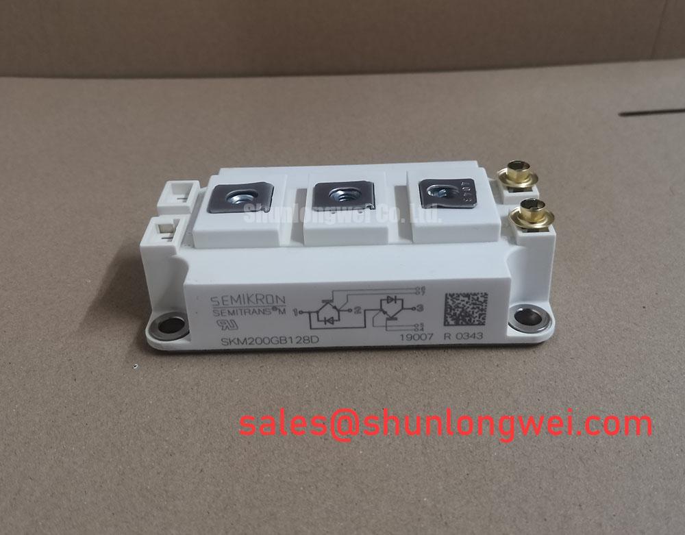
Measure the cold resistance between the documented power terminals, then check each documented diode path in the specified polarity before connecting SKM111RZR to a driver. Record the meter range, probe orientation and readings alongside those from a known-good unit. A diode-mode indication is useful for spotting a short or an unexpected open path; it is not a substitute for a switching test. Confirm the terminal map from the module documentation rather than assuming that another SEMITRANS unit has the same internal circuit.
The supplied factory data identifies a 200.0 A current rating (Official Specification) and a SEMITRANS package. It does not establish a numerical blocking-voltage rating, surge-current limit, junction-temperature limit or transient thermal impedance for this part. Those limits matter when a controller reports an overload: a steady current rating alone cannot show whether a short pulse leaves adequate junction-temperature margin or how long the device needs to cool before another pulse.
For a controlled bench evaluation, capture current, voltage and case temperature over the actual overload sequence. As an Engineering Calculation, pulse-by-pulse junction-temperature estimates require measured power loss and the applicable junction-to-case transient thermal impedance; a multi-RC model is useful only when its coefficients describe the module being assessed. Compare the resulting peak and recovery profile with the documented limits. Keep the switching-current loop compact to reduce inductive overshoot, and confirm the achieved margin from captured waveforms rather than a layout rule of thumb. The Semikron-Danfoss SEMITRANS product information provides package-family context, not a substitute for part-specific limits.
Transient Dynamics & Electrical Design: High-Altitude Cosmic Ray Induced SEB Failure on SKM111RZR
Probe the DC link and the module terminals during turn-off, and compare the captured peak with the documented blocking-voltage limit for SKM111RZR. The provided specification calls its voltage class “Standard Industrial Rating” but gives no numerical value, so it cannot establish voltage headroom. Check the scope probe arrangement for loop pickup before treating a narrow spike as a device-terminal event.
Altitude and radiation-related single-event burnout are separate reliability questions from an observed switching overshoot. Without a part-specific qualification source and operating-voltage profile, no FIT rate, altitude derating or SEB threshold can be assigned to this module. As a Design Consideration, a system engineer evaluating a high-altitude installation should obtain the applicable manufacturer guidance and assess the actual DC-link stress against it; a benign bench waveform does not resolve a long-term reliability question.
Where the equipment uses phase-angle control or exhibits line-frequency bus ripple, inspect the controller timing and DC-link waveform before attributing irregular module current to the IGBT. If turn-off ringing is present, compare gate voltage, collector-emitter voltage and current on the same timebase. Gate-loop inductance, driver impedance and an external RC snubber can affect the waveform, but snubber values and clearance requirements belong to the complete system design. Tune against measured loss, voltage stress and board geometry. Confirm whether the documented terminal arrangement provides an auxiliary emitter connection before planning a separate gate-return route; the package name alone does not establish one. The Semikron-Danfoss power modules catalog is a useful starting point for locating the relevant module documentation.
Benchtop Waveform Tuning: Mitigating Stress via Bi-Directional DC-DC Buck-Boost Conversion on SKM111RZR
Capture gate and power-terminal waveforms at both directions of current transfer in the proposed DC-DC stage, then check whether a controller transition produces an unexpected current reversal or turn-on. A commercial string inverter or micro-grid battery interface is a possible compatibility assessment, not a confirmed application for SKM111RZR. The module’s documented circuit, voltage rating and thermal limits must match the intended converter before its 200.0 A rating can inform that assessment.
During repetitive peak-shaving operation, log case temperature with current and switching activity. Repeated thermal swings can be missed by a single full-load snapshot; use the equipment’s actual duty sequence when checking junction-temperature margin. If the gate waveform rings, inspect the driver return path and its relationship to the power-current loop. Miller coupling during a rapid voltage transition may contribute to unwanted gate movement, but its significance depends on the documented device characteristics and the installed driver. Evaluate any active-clamp function against measured transients rather than assuming one is required.
If the driver uses a bootstrap supply, measure its voltage through the longest operating intervals and during rapid cycling. Charge replenishment and diode recovery are driver-circuit questions that cannot be settled by the module current rating. For a candidate comparison, SKM100GB063D can be assessed alongside SKM111RZR; it is not established here as a direct replacement. Compare documented circuit configuration, terminal placement, voltage and current limits, gate requirements, mounting interfaces and thermal performance before considering interchangeability.
SKM111RZR Thermal-Electrical Optimization: Thermal Interface Material Thickness Uniformity Practical Tuning
Inspect the heatsink contact area and the module mounting face for debris, damage or uneven contact before applying thermal interface material. Spread the material uniformly without prescribing a thickness from package-family information alone. Excess material and unfilled areas can both affect the thermal path; use the mounting procedure and interface-material guidance applicable to the actual assembly.
Tighten mounting screws in the documented sequence and to the specified torque, then recheck seating without treating baseplate curvature as a defect by default. 💡 Bench Tip: Disconnect and discharge the DC link before touching module terminals or moving gate-probe leads. On the bench, maintain ESD precautions at the gate terminals and retain the cold diode-mode readings as a baseline for later service measurements.
If case temperature rises unexpectedly in service, first compare sensor placement, coolant or heatsink conditions, mounting contact and measured switching loss. A temperature rise does not identify a single cause. As a Design Consideration, review the interface and heat-flow path before changing driver settings; The Advanced Thermal Management Revolution provides broader thermal-management context. Any insulation withstand check should follow the documented module limits and the facility’s controlled test procedure rather than an assumed SEMITRANS-wide voltage.