

Content last revised on October 16, 2026
SKM145GB124DN Circuit Protection & Reliability: Assessing High-Frequency Common-Mode Bearing Current
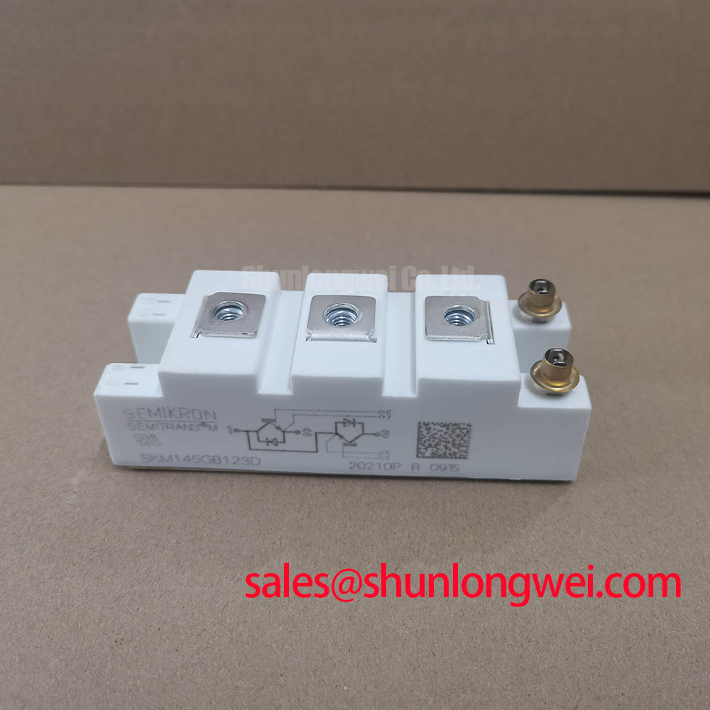
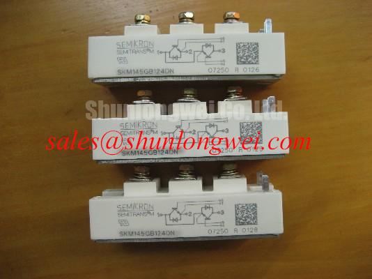
With the DC link isolated and discharged, check the gate-driver connections and power-terminal routing before investigating repeated trips around the SKM145GB124DN. The Semikron IGBT module is identified as a 1200 V, 145 A device in a Semitrans package. These identify the component’s basic electrical class; the applicable datasheet conditions must be checked when assessing current capability. Replacement assessment also requires matching its circuit configuration, terminal arrangement, cooling interface, and driver requirements to the equipment drawings.
Compare the switching waveform at the inverter output with the waveform at the load terminals before attributing voltage overshoot to the module itself. As a Design Consideration, long cables behave as transmission lines when switching edges are fast relative to cable propagation time. Impedance mismatch can produce reflected-wave reinforcement approaching twice the incident voltage step under idealized conditions. That is a transmission-line effect, not a guaranteed SKM145GB124DN operating value or an acceptable terminal-voltage limit.
Use appropriately rated differential measurement equipment and document probe placement, cable routing, load condition, and switching settings. Separate differential-mode terminal overshoot from common-mode displacement current: they can occur together but require different diagnostic evidence. A current probe around the relevant return path can help identify high-frequency common-mode circulation, while shaft-voltage measurements require a suitable measurement arrangement. Bearing noise or repeated trips alone do not establish bearing-current damage.
As a Design Consideration, an output dv/dt filter should be evaluated against cable characteristics, load insulation requirements, switching frequency, and permissible voltage drop. Common-mode chokes address a different current path and should not be treated as interchangeable with differential-mode filtering. Filter selection belongs to the complete drive system, including resonance, heating, leakage-current paths, and protective-earth connections. Preserve the equipment’s specified clearances when adding components; electrical spacing cannot be selected from the module’s voltage rating alone.
Commutation behavior also deserves attention when investigating ringing. In general power-semiconductor analysis, diode reverse-recovery softness describes the recovery waveform shape and can influence excitation of parasitic resonances. No softness factor is assigned here to the SKM145GB124DN. Instead, compare measured recovery-related current and voltage waveforms under representative operating conditions. Changes in temperature, commutation current, gate drive, and loop inductance can alter the observed result.
Fourier series decomposition for inverter output waveform harmonic analysis provides mathematical background for interpreting periodic waveform harmonics. It does not establish radiated-emissions compliance or replace switching-edge measurements. Distinguish lower-frequency output harmonics from high-frequency ringing before choosing a corrective measure.
For topology-dependent switching-margin assessment, Resonant Topologies in Home Appliances offers complementary context on resonant and half-bridge operation. Its application context is different; use it to understand commutation conditions, not as an acceptance standard for this module. Evaluate measured collector-emitter stress against the applicable device limits throughout the intended operating envelope.
Assembly Integrity & Layout Architecture: Implementing Gate Driver Auxiliary Power Sequencing for SKM145GB124DN
Establish a valid gate-driver auxiliary supply and a defined off-state before enabling the high-voltage DC link. As a Design Consideration, the control sequence should inhibit switching while driver supplies are starting, outside their valid range, or collapsing. Check undervoltage-lockout behavior at both startup and shutdown, including interrupted auxiliary power and reset conditions. A logic-level disable command is insufficient evidence if the output stage loses its ability to hold the gate off.
Where the selected driver architecture uses negative gate bias, choose that bias from the module’s permitted gate-voltage limits and the driver’s operating requirements, then validate the actual gate-emitter waveform. A generic negative-voltage range is not a specification for the SKM145GB124DN. Measure at the module connections with a low-inductance probing arrangement so that common-mode pickup is not mistaken for gate motion.
Miller-induced gate disturbance depends on collector-voltage slew rate, gate-loop impedance, and device capacitance. Reverse-transfer capacitance, often designated Cres, is not interchangeable with Miller charge; capacitance varies with operating voltage, while charge describes an integrated transition. As a Design Consideration, evaluate gate discharge capability and any Miller-clamp function against measured off-state excursions. Collector-side active clamping serves a different protection purpose and requires separate assessment of switching energy and protection coordination.
Practical tip: Keep the commutation path compact and balanced, then verify turn-off overshoot and off-state gate stability in a controlled double-pulse test before increasing operating stress.
Keep driver return currents separate from power-current paths wherever the documented terminal arrangement permits. Route gate and return conductors together, and assess shield termination against the equipment grounding architecture. Common-mode ground movement can disturb control signals even when the average auxiliary voltage appears correct. Appropriate isolation, spacing, and layout depend on the complete assembly and its applicable requirements.
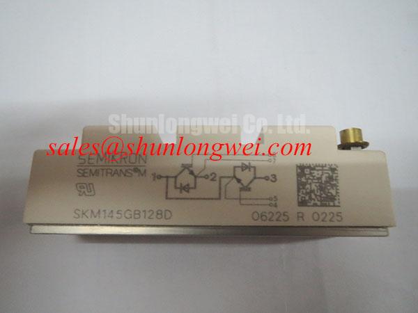
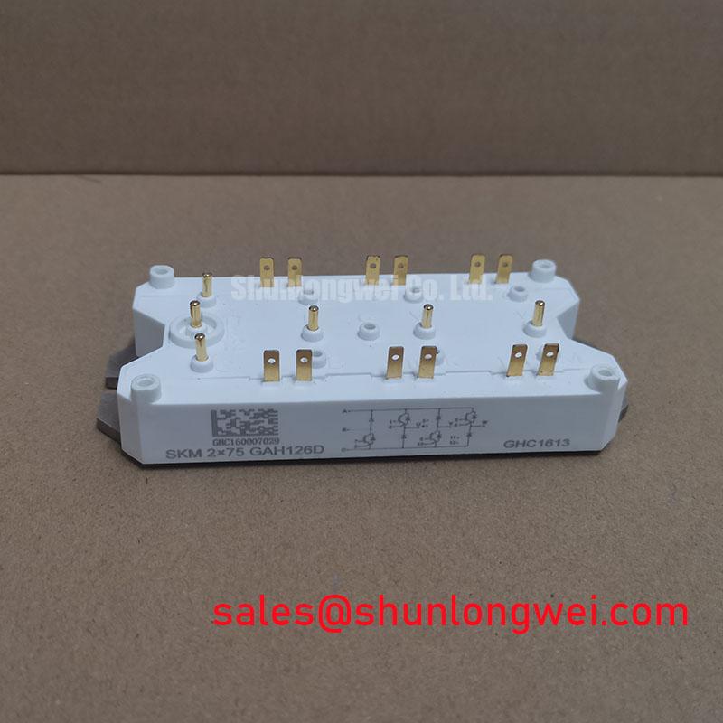
A replacement review should compare interfaces before considering a different part number. For example, the SKIM401GD128D can be included in a broader Semikron sourcing comparison, but the link does not establish electrical or mechanical interchangeability. The following comparison lists basic device information alongside items requiring datasheet review.
| Comparison item | SKM145GB124DN | SKIM401GD128D |
|---|---|---|
| Manufacturer | Semikron | Semikron |
| Rated voltage | 1200 V | Consult datasheet |
| Rated current | 145 A — check applicable datasheet conditions | Consult datasheet |
| Package designation | Semitrans | Consult datasheet |
| Replacement acceptance | Match equipment interfaces and operating conditions | Compare topology, terminals, driver needs, dimensions, and cooling interface |
For semiconductor-fuse coordination, evaluate the fuse’s total clearing I²t, interrupting capability, circuit voltage, and prospective fault current alongside the equipment’s protection design. Do not infer an IGBT short-circuit withstand capability from a diode surge-current rating. Fast electronic fault detection and controlled shutdown address a different timescale from fuse clearing. A semiconductor fuse cannot be assumed to prevent module rupture during every short-circuit event; the assembly’s containment and protection coordination require system-level assessment.
SKM145GB124DN Thermal-Electrical Optimization: Heatsink Surface Flatness and Thermal Grease Application
Inspect the heatsink contact surface for burrs, contamination, and local distortion before positioning the SKM145GB124DN. As a Design Consideration, assess module mounting-face geometry against the applicable assembly drawing rather than assuming that visible curvature is a defect or attempting to flatten it mechanically. The package designation alone does not establish baseplate material, permissible flatness, or mounting torque.
Apply the selected thermal interface material using a repeatable process consistent with the module mounting instructions and the material supplier’s guidance. Coverage, surface condition, and clamping pressure determine the installed interface; a universal grease thickness is not appropriate. Where the specified fastening procedure uses progressive diagonal tightening, follow its sequence with a calibrated tool. Tightening harder to compensate for poor contact can introduce mechanical stress without resolving the underlying interface problem.
Assess thermal performance through repeatable measurements at defined load, cooling, and ambient conditions. A low heatsink temperature does not by itself demonstrate adequate junction-temperature margin: poor interface contact can leave the heatsink relatively cool while semiconductor temperatures rise. Compare temperature trends across operating points and inspect contact evidence when the assembly is safely dismantled.
For pulsed operation, use the applicable transient thermal impedance, Zth, with the actual loss history and its specified reference boundary. As a Design Consideration, a single steady-state thermal resistance cannot describe every short overload. Repetitive pulses also accumulate heat, so pulse duration, repetition, initial temperature, and cooling conditions all affect peak junction temperature. Keep conduction and switching-loss estimates tied to the relevant operating conditions rather than treating rated current as a continuous thermal guarantee.
The manufacturer’s Semikron-Danfoss SKiiP® Technology page illustrates why power-module construction and thermal interfaces are technology-specific. It does not identify the SKM145GB124DN as a SKiiP product or transfer those construction features to it.
When evaluating this module for a heavy-duty variable-frequency AC motor drive, check the existing heatsink interface, airflow or coolant conditions, terminal fit, and driver connections against the equipment documentation. Record the mounting procedure and thermal baseline after installation. If temperatures drift during comparable operation, inspect cooling performance, interface contact, and electrical losses separately before changing the assembly process.