
Content last revised on October 8, 2026
SKM180A020 Replacement Inspection
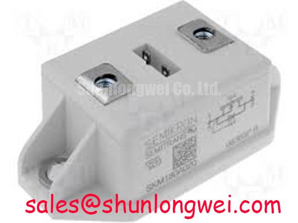
Before reconnecting a replacement, isolate the DC link, inspect the power terminals for heat discoloration, and verify the cold-state impedance path against a known-good assembly. The Semikron SKM180A020 is an IGBT module rated at 1200 V and 180.0 A, with a Semitrans package designation according to the supplied manufacturer data. Those three values define the confirmed product identity here; switching loss, gate charge, thermal resistance, isolation voltage, and transient ratings must be checked against the applicable device documentation before system approval.
In commercial string inverters and micro-grid energy storage converters, a failed power module is rarely isolated from the surrounding mechanical and electrical conditions. A discolored terminal, uneven baseplate contact, cracked insulation interface, or altered gate waveform can cause a replacement module to fail again even when its voltage and current ratings appear suitable. Treat the SKM180A020 as part of a complete switching leg: check the DC-link condition, gate-driver supply, clamping hardware, cooling path, busbar geometry, and protection response before applying full operating power.
Thermal Paste Degradation Prevention and Mechanical Clamping Torque Calibration
Start the mechanical inspection with the heatsink rather than the module. Remove old thermal interface material completely, then examine the mounting surface for raised burrs, embedded particles, corrosion, or local distortion. The Semitrans package designation identifies the package family, but the supplied product data does not specify baseplate flatness, recommended thermal interface thickness, or mounting torque. These values should therefore be taken from the applicable Semikron mechanical drawing or installation instruction rather than copied from another module with a similar outline.
For a repair installation, a thin and continuous thermal interface layer is generally preferable to a thick layer. A practical Design Consideration is to control the applied layer within the material supplier’s recommended range, with 50 to 100 µm used only as a starting reference when the selected interface material and surface condition support it. This is not an SKM180A020 factory specification. Excess compound increases thermal resistance and can migrate toward insulation surfaces; insufficient compound leaves air pockets beneath the baseplate. Apply the material evenly, keep the mounting face clean, and inspect the contact pattern after controlled tightening if the assembly permits that check.
Baseplate curvature compensation must be handled by the actual hardware geometry. Do not attempt to correct a warped heatsink by forcing the module down with excessive bolt load. A distorted mounting plane can concentrate pressure near one edge, leaving the power chips thermally uneven while the fastener appears tight. Use the original mounting points, washers, and specified hardware where available. If the heatsink has been reused after a thermal event, check it with a suitable straightedge and inspect the threaded holes for damage.
Sequential tightening matters because the first fastener can pull the package out of alignment and create a poor interface at the opposite side. Bring all fasteners into light contact, confirm that the module sits naturally on the heatsink, and then tighten in the sequence and stages stated by the relevant mechanical documentation. A generic M5 installation torque of 2.5 to 3.5 N·m may be encountered in industrial assemblies, but it is a general mounting reference, not a confirmed SKM180A020 specification.
⚠️ Field Alert: Never reuse a power module mounting torque by feel after a thermal failure; use a calibrated torque tool and verify that the fastener sequence matches the package drawing.
After mounting, inspect the clearance around the main terminals and gate connections. Busbars should not press sideways against the module terminals, and cable weight should be supported by the enclosure rather than by the terminal hardware. In a vibrating inverter cabinet, add mechanical support to heavy conductors while preserving the creepage and clearance required by the system insulation design. A clean thermal interface cannot compensate for a terminal joint that loosens under vibration.
Insulation Barrier Integrity and Parasitic Coupling Capacitance Reduction
Inspect the isolation barrier before connecting the gate driver. Look for carbon tracking, metal debris, cracked insulating supports, damaged terminal sleeves, and contamination from conductive dust or electrolyte residue. The supplied SKM180A020 data confirms a 1200 V voltage rating, but it does not provide a verified reinforced insulation voltage, common-mode transient immunity value, or certification statement. Do not present values such as greater than 5 kV or greater than 100 kV/µs as device specifications without the applicable datasheet and test conditions.
Isolation performance belongs to the complete assembly. The driver supply isolation, optocoupler or digital isolator, PCB creepage, busbar arrangement, heatsink construction, mounting hardware, and enclosure contamination level all influence the finished system. Designers should verify the required insulation coordination against the relevant equipment standard and test the assembled converter under controlled conditions. The module by itself should not be described as independently certified for system safety or EMC compliance.
Parasitic coupling is best controlled through physical layout. Keep the high-current commutation loop compact, separate sensitive gate-driver traces from fast collector and emitter paths, and avoid routing a gate signal alongside a switching node for unnecessary distance. The purpose is to reduce common-mode displacement current and prevent an apparent gate pulse from being created by the surrounding electric field. The final layout must be validated with the actual bus voltage, switching speed, gate resistance, probe arrangement, and mechanical enclosure in place.
Complementary devices in a bridge leg require clear interlock logic. Dead time is a system design variable determined by gate-driver propagation delay, device turn-off behavior, temperature, load current, and the measured switching waveforms. Set a conservative initial buffer during commissioning, then confirm that both devices are fully off before the opposing command is enabled. Do not copy a dead-time value from a different IGBT module or driver board and treat it as an SKM180A020 parameter.
During fault finding, power the driver separately where the design allows it and observe the gate-to-emitter waveform with an appropriately rated differential probe. Check for excessive ringing, an unstable driver supply, unequal positive and negative gate excursions, or a command that remains active during a protection event. If a suspected isolation test is required, use the voltage, ramp rate, duration, and discharge procedure specified for the complete assembly. Uncontrolled high-voltage testing can damage the module and create a personnel hazard.
The Semikron-Danfoss SEMITRANS® Industry Standard IGBTs reference can help engineers understand the broader package family, but family-level information should not replace the exact SKM180A020 documentation. For system EMC work, the Semikron-Danfoss Power Modules Catalog is a useful manufacturer resource, while final compliance remains the responsibility of the assembled equipment designer.
Multi-Module Parallel Current Sharing and Positive Tempco Dynamic Balancing
Paralleling power modules requires more than matching the printed current rating. The SKM180A020 is specified at 180.0 A, but that rating does not automatically define an acceptable parallel operating point, transient overload capability, or current-sharing tolerance. The system engineer must confirm the permitted topology, cooling arrangement, switching frequency, pulse profile, gate-driver capability, and manufacturer limits before connecting multiple modules in parallel.
For steady-state conduction, the temperature behavior of the IGBT’s saturation characteristic can support passive current balancing in some operating regions. This is a general semiconductor behavior and must be confirmed from the relevant output-characteristic curves at the intended current and temperature. It should not be treated as a guarantee that parallel modules will share evenly during turn-on, turn-off, short-circuit protection, or a sudden load step.
Dynamic balance depends heavily on the gate and power-loop geometry. Use symmetrical conductor lengths, equivalent busbar inductance, and matched gate-driver paths where the circuit topology requires parallel operation. Place the current return path so that one module does not receive a materially different emitter reference from another. A shared gate connection can conceal unequal parasitic inductance; separate damping and monitoring arrangements may be considered when supported by the driver design and the applicable device data.
Before energizing the DC link, compare the gate waveforms at each module location using the same probe type and reference method. Then perform a controlled low-energy switching test and compare collector-emitter voltage, turn-on current slope, turn-off overshoot, and temperature rise. A module that runs hotter than its partner may reflect unequal busbar impedance, a poor thermal interface, a gate connection problem, sensor placement error, or a difference in semiconductor characteristics. Treat the observation as a diagnostic lead rather than a single-cause conclusion.
Current sharing should also be checked after the enclosure reaches its intended operating temperature. A cold bench test can hide the effect of heatsink gradients, cable heating, fan airflow imbalance, or thermal contact degradation. Install current measurement equipment so that it does not introduce a significant loop inductance or disturb the original busbar arrangement. Where the converter uses protection thresholds, validate them with the final number of parallel modules and the actual sensor calibration.
When reviewing a different Semikron module for a constrained repair, engineers may examine the SKM100GB124D as a separate product for objective comparison. It should not be considered a drop-in substitute solely because it belongs to the same general power-module market. Voltage rating, current rating, circuit topology, package dimensions, terminal arrangement, gate requirements, thermal interface, and switching characteristics all require independent confirmation before any substitution decision.
Dynamic Power Loss Dissipation and Multi-RC Thermal Ladder Representation
Thermal troubleshooting should begin with measured operating data. Record DC-link voltage, phase current, switching frequency, duty cycle, case temperature, coolant or airflow condition, and the duration of the overload pulse. The confirmed SKM180A020 values in this product record are 1200 V, 180.0 A, and Semitrans package construction. They do not provide the switching energies, conduction voltage curves, thermal impedance curves, or maximum junction temperature needed to calculate a complete loss budget.
For a practical estimate, conduction loss is obtained from the device’s voltage-current characteristic at the relevant temperature and current waveform, while switching loss depends on the manufacturer’s energy data and the actual voltage, current, gate resistance, temperature, and circuit stray inductance. Do not multiply the 180.0 A rating by 1200 V and interpret the result as usable module power. Those are boundary ratings, not a continuous dissipation value.
A multi-RC thermal ladder can represent the transient path from junction to case, but its resistance and time-constant values must come from the applicable thermal impedance data. In a field repair, apply the measured power pulse to the documented transient thermal model, add the case-to-heatsink and heatsink-to-ambient or coolant path, and compare the calculated junction temperature with the manufacturer’s permitted limit. If the required thermal curves are unavailable, report the calculation as incomplete rather than inventing a junction margin.
Heavy pulsed overloads deserve separate attention because the case may remain cool while the semiconductor junction experiences a rapid temperature rise. Use pulse duration and repetition rate to identify whether the dominant thermal response is short-term junction heating or longer-term heatsink accumulation. A thermocouple attached to the case can support trend monitoring, but it cannot directly measure junction temperature. Infrared measurements also require attention to emissivity, surface finish, and line of sight.
When a repaired inverter trips again, compare the thermal and electrical records rather than replacing the module immediately. Check whether the gate command is clean, whether the DC-link overshoot remains within the system design boundary, whether cooling airflow is balanced, and whether the module baseplate temperature follows the expected load pattern. Inspect the snubber and clamp network for degraded components, since a damaged suppression path can increase switching stress without leaving obvious marks on the IGBT body.
For structured fault analysis, the Field Engineer’s Handbook provides a broader framework for testing, failure analysis, and reliability review. Use that type of procedure to document measured waveforms, thermal conditions, mechanical findings, and protection events. Any prediction of service life, failure rate, cosmic-ray robustness, altitude derating, or field reliability requires a qualified source and defined test conditions; it should not be inferred from the SKM180A020 nameplate ratings alone.