

Content last revised on October 30, 2026
SKM300GAL128D Identity and Pre-Energization Checks
- Isolate the equipment, discharge the DC link, and verify absence of voltage before checking collector, emitter, and gate connections.
- Disconnect the gate driver before comparing cold terminal measurements with the circuit diagram and a known serviceable assembly.
- Inspect the module mounting surface, terminal seating, and heatsink contact for distortion, contamination, or loose hardware.
- Check driver auxiliary power and fault interlocks before authorizing DC-link energization.
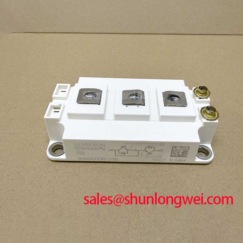
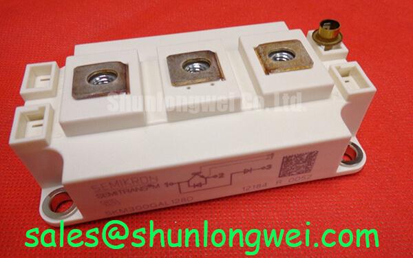
The SKM300GAL128D is a Semikron IGBT module with a GAL low side chopper configuration in a SEMITRANS 3 package. Establish that circuit identity before evaluating a replacement: matching voltage and current markings alone does not establish terminal or topology compatibility.
| Feature or parameter | Official Specification |
|---|---|
| Collector-emitter voltage, VCES | 1200 V |
| Collector current at case temperature 25°C | 300 A |
| Collector current at case temperature 80°C | 215 A |
| Typical collector-emitter saturation voltage | 1.70 V |
| Typical turn-off switching energy | 28 mJ |
| IGBT junction-to-case thermal resistance | 0.11 K/W |
| Configuration | GAL low side chopper |
| Package | SEMITRANS 3 |
The typical saturation voltage and switching energy are conditional characterization values; consult the datasheet test conditions when comparing losses. Junction-to-case thermal resistance covers that thermal path, while heatsink contact and cooling performance require separate assessment.
SKM300GAL128D Operational Boundaries: Driver Power Stage Startup and Inrush Mitigation
Check that auxiliary driver power establishes a controlled gate-off state before the DC link rises. As a Design Consideration, observe the driver supply, gate-emitter voltage, enable signal, and undervoltage lockout response through startup and shutdown. If the existing circuit uses negative turn-off bias, verify its establishment and decay against the driver specification and equipment sequencing.
Keep DC-link precharge and gate-driver readiness as separate checks. Precharge limits capacitor charging current; a stable gate-off state prevents unintended conduction while bus voltage develops. A startup trip warrants inspection of both functions rather than assuming the module itself caused the event. Confirm that loss of auxiliary power inhibits switching through the intended interlock path.
For compatibility assessment, engineers may evaluate this module within industrial inverter welders or medium-frequency induction heating supplies where the schematic requires a low side chopper. In regenerative braking circuits, assess braking-resistor connections, energy handling, and control logic separately from the semiconductor rating. These are equipment-level compatibility checks, not dedicated application guarantees.
When comparing the SKM200GAL126D, check its own current ratings, circuit arrangement, terminal drawing, driver requirements, and thermal limits. A related model designation provides a comparison candidate without establishing interchangeability.
SKM300GAL128D Thermal-Electrical Optimization: Isolated DC-DC Power Supply Sizing
Evaluate the isolated driver supply against the installed switching duty and the isolation requirements of the complete assembly. As an Engineering Recommendation, check output regulation during gate charging, auxiliary consumption, and fault recovery. Supply sizing depends on gate-charge demand, switching frequency, driver losses, and the selected gate-voltage swing; the module’s collector-current rating does not specify auxiliary supply power.
Assess the isolation barrier using documented working-voltage capability, insulation classification, creepage, clearance, and transient conditions. A withstand-test voltage alone does not establish suitability for continuous operation. Select driver and supply components with documented common-mode transient performance appropriate to measured switching edges, then check whether disturbances propagate into enable or fault signals.
Where the surrounding converter has complementary switching devices, examine command interlocks and propagation delays before adjusting dead time. The GAL module itself must not be treated as a complete half bridge. Validate non-overlap across the actual driver paths, including behavior during undervoltage and fault reset.
Restore consistent baseplate-to-heatsink contact using the specified interface material and mounting procedure. Field Alert: Apply the documented mounting torque and tightening sequence, and keep the thermal interface uniform rather than compensating for poor contact by overtightening. Package drawings and manufacturer application guidance are available through the Semikron-Danfoss Power Electronics & Modules Official Hub.
SKM300GAL128D Thermal-Electrical Optimization: High dv/dt and Unintended Turn-On
Measure gate-emitter voltage at the module connection while observing collector-voltage transitions, using probes suitable for the measurement environment. As a Design Consideration, a gate excursion during an off command warrants investigation of capacitive coupling, driver sink impedance, and shared return inductance. Distinguish a real gate disturbance from probe pickup before changing components.
An active Miller clamp can provide a local discharge path when supported by the selected driver. Negative off-bias can also improve turn-off immunity, subject to gate limits and driver capability. The Evolution of Negative Off-Bias Gate Drive Circuits explains the circuit principles behind that assessment.
Keep the gate loop compact and separate its return from disruptive power-current paths. Where laminated busbars are used, inspect joint seating and current-loop geometry to reduce parasitic inductance and turn-off overshoot. Validate changes by observing gate disturbance and collector-voltage peaks under the equipment’s intended operating conditions; adjust damping and driver settings from those measurements.