
Content last revised on October 16, 2026
SKM75GB063D Replacement Assessment and Pre-Installation Checks
- Confirm the unpowered main terminal and antiparallel diode readings with a digital multimeter in diode check mode.
- Inspect the Semitrans baseplate, heatsink contact area, thermal interface material, and mounting hardware before installation.
- Verify the gate, emitter, and auxiliary return connections against the equipment wiring and module terminal drawing.
- Check driver isolation, gate loop routing, and protection timing before applying DC-link voltage.
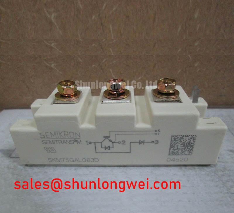
The Semikron SKM75GB063D is a 600 V IGBT half-bridge module, with a specified collector current of 75 A at a case temperature of 75 °C and junction temperature of 150 °C, supplied in a SEMITRANS 2 housing. For a replacement assessment, begin with cold electrical screening and mechanical interface checks rather than energizing the traction inverter immediately. ([eytsa.com](https://eytsa.com/wp-content/uploads/2020/06/SEMIKRON_DataSheet_SKM75GB063D_22890050-1.pdf))
| Manufacturer | Semikron |
| Part number | SKM75GB063D |
| Product category | IGBT half-bridge module |
| Collector-emitter voltage rating | 600 V at Tj = 25 °C |
| Specified collector current | 75 A at Tcase = 75 °C, Tj = 150 °C |
| Package | SEMITRANS 2 |
These ratings are listed in the manufacturer's datasheet and are not recommended system operating conditions. Switching frequency, gate voltage, short-circuit withstand behavior, thermal resistance, isolation rating, and terminal geometry should be matched with the applicable technical documentation before a production replacement is approved. ([eytsa.com](https://eytsa.com/wp-content/uploads/2020/06/SEMIKRON_DataSheet_SKM75GB063D_22890050-1.pdf)) The Semikron-Danfoss SEMITRANS® Industry Standard IGBTs reference provides useful context for the package family and power module integration.
Assembly Integrity and Layout Architecture: Implementing Unpowered Bench Screening with a Multimeter
Cold screening should separate a healthy-looking module from a unit requiring further investigation before any DC energization. Isolate the equipment from all power sources, discharge the DC link through the equipment’s approved discharge path, verify the absence of voltage, and disconnect the module from external power wiring and gate-driver connections. With appropriate ESD precautions, short each gate to its corresponding emitter during collector-emitter diode checks to prevent stored gate charge from turning the IGBT on. A digital multimeter in diode mode can then be used across each collector-emitter pair in both polarities to check the antiparallel diode and look for a short circuit. Record polarity, displayed forward voltage, and whether the instrument reports an open circuit in the reverse direction. ([assets.danfoss.com](https://assets.danfoss.com/documents/latest/444231/AB501643313479en-000201.pdf?utm_source=openai))
The result should be interpreted comparatively rather than through a universal pass or fail number. Compare corresponding paths within the same module and, where available, against a known-good unit from the same equipment family. An unexpected open reading in the diode’s forward direction, a near short in both polarities, or a strong imbalance between equivalent paths warrants a second measurement with all external wiring removed.
Gate insulation screening requires the gate terminal to remain electrically isolated from the driver board, with any temporary gate-emitter short removed. Using an appropriate low-voltage resistance range, measure between gate and emitter, then repeat after reversing the leads. A low-impedance indication may point to contamination, an incorrect terminal reference, or damage in the gate structure, but the meter alone cannot establish dynamic switching condition or verify the specified gate leakage. Observe ESD precautions, keep the instrument’s test voltage within the gate rating, and avoid applying an external gate supply during this cold check. Discharge the gate to its corresponding emitter after testing. ([assets.danfoss.com](https://assets.danfoss.com/documents/latest/444231/AB501643313479en-000201.pdf?utm_source=openai))
In a forklift or electric material-handling traction inverter, the module is commonly evaluated alongside the DC-link capacitors, busbar joints, freewheel paths, current sensors, and gate-driver board. A replacement assessment should therefore include inspection for carbon tracking, loose laminated busbar joints, and damaged driver connectors. The MG75G1JL1 may be reviewed as a separate component reference, not as an automatic substitute for the SKM75GB063D.
⚠️ Maintenance Note: Keep the module disconnected from the driver while performing bench measurements, because an external gate signal can invalidate the reading and create an avoidable switching hazard.
Assembly Integrity and Layout Architecture: Implementing Baseplate Thermal Grease Layer Control
Thermal installation begins with a clean, flat mating surface on both the Semitrans baseplate and the heatsink. Remove cured compound without scoring the metal, then inspect for burrs, raised edges, embedded particles, and visible curvature. The purpose of the thermal interface material is to fill microscopic surface irregularities, not to compensate for a visibly uneven heatsink or a distorted mounting plate.
Engineering Recommendation: A controlled thermal compound layer in the approximate 50 to 80 µm range can be used as a starting process target when the selected material and surface finish support it. This is a process-development suggestion, not a specified mounting requirement for the SKM75GB063D; follow the applicable module mounting instructions and thermal interface material guidance. The final method remains system dependent because compound viscosity, baseplate flatness, application tool, and clamping behavior affect the achieved layer. Excess compound can increase the thermal path and migrate toward nearby insulation surfaces.
Apply the material evenly across the active contact area, keeping the layer continuous without ridges or unfilled regions. A practical production check is to trial-fit the module, apply the approved clamping sequence, and inspect the transfer pattern after removal during process validation. Voids or a narrow transfer band indicate poor surface contact, uneven pressure, or an unsuitable application quantity.
Mounting screws should be tightened progressively in the sequence specified by the applicable mounting instructions so that the baseplate approaches the heatsink without forcing one corner down first. Where the assembly uses flat pressure hardware or disc springs, verify the spring orientation, seating condition, and calibrated compression against the equipment’s mechanical specification. The clamping system should distribute force across the baseplate rather than concentrate load near a single fastener.
After installation, inspect the heatsink airflow path and confirm that adjacent components do not obstruct the cooling surface. During preventive maintenance, compare contact temperature behavior between matching phases under equivalent load. A rising phase-to-phase temperature difference can justify a controlled inspection of compound aging, fastener preload, fan performance, and dust accumulation before the module is condemned.
Assembly Integrity and Layout Architecture: Separating Driver Return from Main Current
The gate-driver return must follow the terminal arrangement intended for the module rather than sharing a long, high-current emitter path. During commutation, voltage developed along the load-current connection can shift the driver’s local reference. That ground bounce can appear as an unwanted gate signal, slower turn-off, or oscillation at the gate waveform.
Where the terminal layout provides an auxiliary emitter return, route that return directly to the driver reference and keep it separate from the power emitter connection until the intended electrical joining point. Do not route the gate trace alongside a high-current collector or emitter busbar for unnecessary distance. Minimize the physical area of the gate loop, maintain the required insulation clearance from the DC-link conductors, and place the gate resistor and any damping network according to the driver architecture.
Gate-loop parasitic inductance can interact with device capacitance and produce ringing during turn-on or turn-off. An engineering evaluation should use an oscilloscope with a suitable differential or isolated probing method, checking the gate-to-emitter waveform at the module terminals rather than only at the driver output. The system designer should adjust damping, switching speed, and layout only after reviewing the measured gate waveform, collector-emitter overshoot, and device temperature under the actual load.
Desaturation protection, soft turn-off, short-circuit safe operating behavior, and driver dead time belong to the complete inverter protection system. The SKM75GB063D’s 600 V rating and specified 75 A collector current do not by themselves define the controller’s fault response or a guaranteed short-circuit interval. The protection circuit should detect abnormal collector-emitter behavior, turn the affected IGBT off in a controlled manner, and coordinate dead time so that opposing switches do not conduct simultaneously. Any microsecond-scale blanking or buffer interval must be established from the driver, sensor, wiring, and switching measurements.
For replacement evaluation, compare the terminal mapping, gate-driver reference, mechanical envelope, and protection behavior before approving a different device. The SKKE162/18 is a rectifier diode module, not an IGBT replacement for the SKM75GB063D. ([semikron-danfoss.com](https://www.semikron-danfoss.com/products/p/skke-16218-230b1538?utm_source=openai)) For any candidate IGBT replacement, voltage, current, package, gate characteristics, thermal path, and control timing must be checked independently. The practical integration principles are also collected in IGBT Design and Integration.
For additional manufacturer-level power electronics references, consult the Semikron-Danfoss Power Electronics and Modules Official Hub. In industrial traction equipment, final commissioning should include a controlled low-energy switching test, inspection of gate-return behavior, and verification that the cooling assembly remains mechanically stable after thermal cycling.