



Content last revised on September 10, 2026
Radiated Emissions and System-Level Grounding
Pixel jitter, intermittent horizontal bands, or image disturbance appearing near variable-frequency motor drives should be investigated as a system-level noise coupling issue rather than attributed to the TLX-1301V alone. CISPR Class A and Class B compliance applies to the completed equipment, not to an individual display module. The display’s cable route, controller board, metal backplate, enclosure seams, power conversion stage, and grounding architecture all affect the final radiated and conducted emissions result.
Design Consideration: where the host display architecture uses a shielded FFC or LVDS cable, the cable shield should be terminated according to the equipment grounding design so common-mode interference has a controlled return path. Multi-point bonding to a conductive backplate can be evaluated where cable length, enclosure geometry, and drive noise make a single-point connection ineffective. Ferrite suppression may also be assessed at the cable entry point, with verification by observing the actual image and signal integrity during motor-drive operation.
PWM backlight dimming can introduce audible noise or visual flicker when its frequency, duty-cycle behavior, driver topology, and camera exposure conditions are poorly matched. The required dimming behavior is system-determined and should be confirmed from the original display and backlight documentation. During commissioning, compare the panel image with a known-good display path while the adjacent drive runs through its normal operating range.
For broader background on display selection, interface handling, and system-level checks, see The Ultimate Guide to Industrial TFT LCD Technology.
Thermal Cycling and Display Seal/Gasket Integrity
When a cabinet operates through repeated cold starts and high-temperature shutdowns, inspect the visible panel perimeter, bezel gasket, and mounting surfaces for changes that could permit dust entry, moisture migration, or uneven pressure on the display. Low temperature can slow liquid-crystal response, while thermal expansion differences between a panel, bezel, and chassis can concentrate stress at mounting points. These are system integration concerns and are not individual factory ratings for the TLX-1301V.
Design Consideration: tighten mounting hardware in an even sequence so the bezel load is distributed rather than concentrated at one corner. Uneven clamping can contribute to local optical non-uniformity, pressure marks, or light leakage. The enclosure gasket should sit flat without folds, contamination, or displaced sections that compromise the intended dust and moisture barrier.
Where differential display signalling is used by the host equipment, the cable and PCB path should preserve the impedance and pair matching required by the original controller specification. A disturbed image after a panel change may indicate a connector seating issue, cable damage, incorrect data path, or signal-integrity problem. Verify these conditions with the original schematic and, where available, an oscilloscope comparison against a known-good signal path.
⚠️ Maintenance Note: Inspect cabinet cooling passages and bezel gasket condition during scheduled service, because trapped dust and moisture can shorten the usable stability of the complete display assembly.
Thermal management principles are often discussed alongside thermoelectric transport concepts; the thermoelectric effect provides general technical context, although it does not establish a thermal rating for this display module.
Interface, Timing, Pixel Clock and Skew Compensation
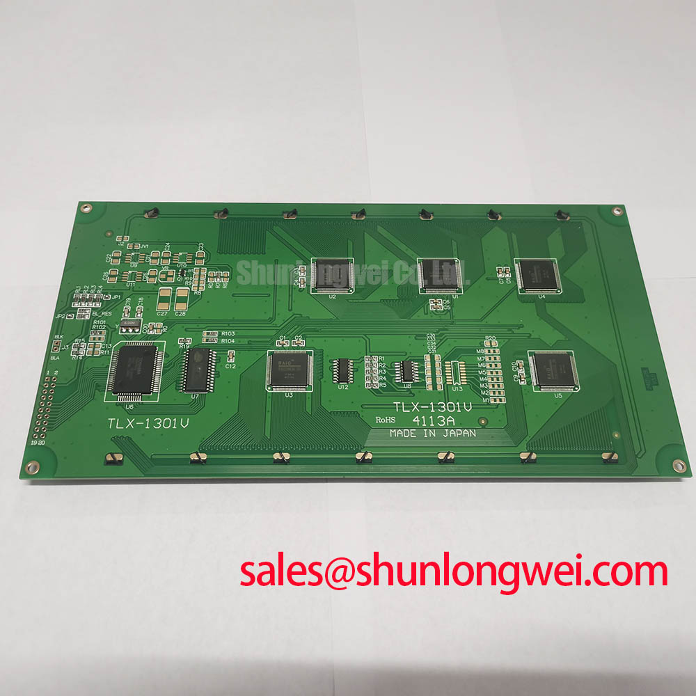
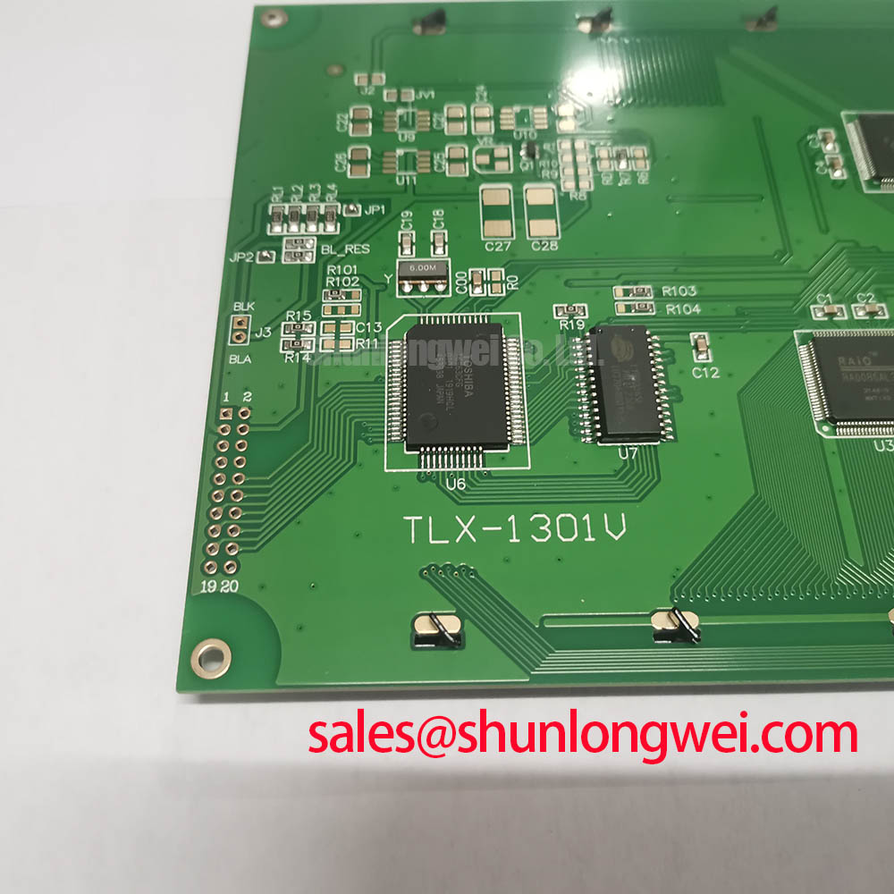
Do not infer the connector count, supply voltage, LVDS format, pixel clock, or JEIDA/VESA data mapping for TLX-1301V from its model name. The system integrator should verify the required supply voltage and interface definition from the original panel documentation and the existing host controller before connection. Applying an assumed pinout or power sequence can create a no-image condition and may place the replacement process at risk.
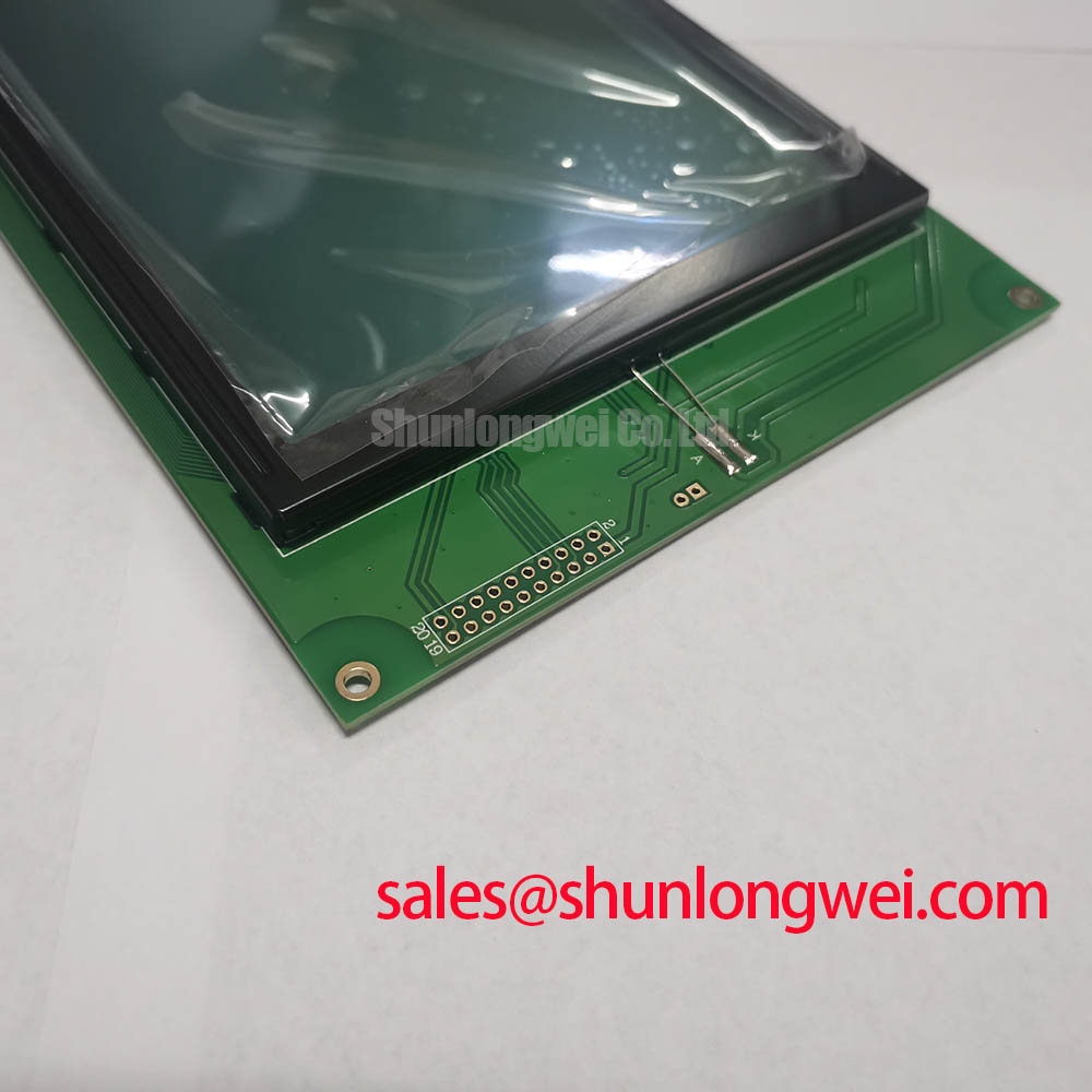
During a controlled repair, first compare the original panel label and connector orientation with the replacement unit. Then confirm that the host cable reaches the connector without twisting, excessive tension, or contact-side loading. Power should be removed before connecting or disconnecting display cables. After installation, check for stable startup, correct image placement, full active-area rendering, and repeatable operation through several power cycles.
If an existing machine uses a separate display solution or related panel architecture, NL12876BC26-21 can be reviewed as a neutral reference for equipment-level comparison. Compatibility must be established from documented electrical, optical, mechanical, and interface requirements; similar product categories do not establish interchangeability.
Split-screen artifacts, color errors, repeating vertical patterns, or an image that appears only after repeated startup attempts should be treated as evidence for structured verification. Check controller output configuration, cable seating, panel enable conditions, supply behavior, and data mapping before replacing additional parts. For waveform terminology used in signal analysis, the Fourier series reference offers general mathematical background and is not a specification source for this module.
Surface Finish, Optical Behavior and High-Ambient Readability
Do not assume that the TLX-1301V includes an anti-glare coating, anti-reflective treatment, a specified contrast ratio, or a particular viewing-angle technology unless those features are confirmed in the original factory documentation. Surface finish, brightness, optical behavior, and sunlight readability are panel-specific properties. The installed front window, bezel depth, protective overlay, and ambient illumination can substantially alter what an operator sees.
For equipment exposed to bright work areas, evaluate readability with the actual enclosure assembled. Clean the viewing window and display surface using a method approved for the machine’s materials, then inspect the image from normal operating positions. Haze, reflections, apparent grayscale reversal, or inconsistent viewing behavior can result from the panel, external cover lens, contamination, controller settings, or mechanical stress. A direct comparison with the removed assembly helps isolate the source without assuming a single cause.
Potential applications may include industrial HMI assemblies and earthmoving-equipment telematics displays, subject to confirmation of the original mechanical envelope and electrical interface. When a maintenance team needs to compare another display option during a documented replacement review, NL128102BC28-04 can be assessed against the equipment requirements. The final decision should be based on verified drawings, interface documentation, optical requirements, and installation testing.