Content last revised on October 15, 2026
TM101JDHG30 Identification and Pre-Installation Checks
- Disconnect display power before inspecting the TM101JDHG30 label, cable orientation, connector seating, and mounting hardware against the equipment service record.
- Check bezel clearance, gasket seating, and chassis flatness for contact that could load the display unevenly.
- Inspect the enclosure for condensation, blocked ventilation, and contamination around cable entries before reconnecting the assembly.
- Record the existing image defect, brightness setting, and equipment temperature so subsequent checks use comparable conditions.
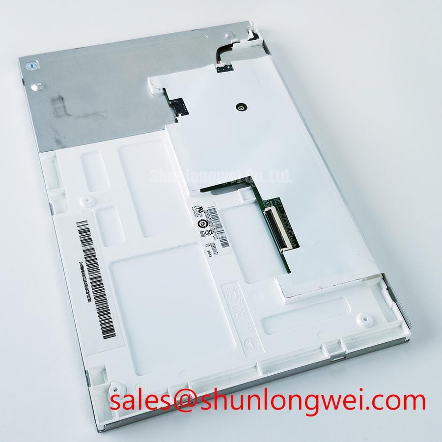
The Tianma TM101JDHG30 is a TFT-LCD active matrix color display module identified for industrial LCD and HMI evaluation. Replacement assessment should connect the panel identity to the host controller, mechanical drawing, and backlight circuit before installation. A matching connector outline alone does not establish electrical or optical compatibility.
| Product identity | Specification |
|---|---|
| Model | TM101JDHG30 |
| Manufacturer | Tianma |
| Product category | Industrial LCD/HMI panel |
| Module construction | TFT-LCD active matrix color display module |
| Electrical, optical, and mechanical ratings | Consult Datasheet for supply voltage, interface, resolution, dimensions, temperature limits, backlight specification, and mounting requirements. |
Checking Localized Compression Effects on Dark Screen Fields
Inspect a uniform dark image with the assembly supported in its intended mounting position, then compare the pattern before and after enclosure fastening. As a Design Consideration, a bright patch that changes with assembly pressure warrants checking bezel contact, gasket overlap, and chassis distortion. This observation helps locate mechanical sensitivity without assigning the defect to an unverified internal layer.
Check the enclosure drawing for clearance around the module perimeter, connector exit, and cable bend. A gasket should follow its intended sealing land without transferring concentrated pressure onto the viewing area. Tighten mounting hardware progressively in an opposing sequence where the enclosure arrangement permits, using the torque specified for the actual joint. Fastener size alone does not establish an acceptable panel mounting torque.
Repeat the image inspection after the enclosure reaches its normal operating temperature. Compare dark fields and neutral gray fields with brightness held constant; changing backlight settings can obscure whether an improvement came from mechanical adjustment or illumination. Record whether the pattern follows an enclosure edge, mounting point, or image content.
Maintenance Note: Inspect ventilation paths and perimeter gaskets during scheduled service, replacing displaced or deteriorated seals before closing the enclosure.
For replacement comparison, evaluate TX18D210VM0BAA against the same mechanical and electrical checklist. Its inclusion is a comparison reference; interchangeability requires agreement on mounting, active area, interface, timing, and backlight connections.
VESA vs. JEIDA Data Mapping Alignment & Even/Odd Channel Signal Integrity
Identify the host video interface and connector pin assignment before interpreting split images or incorrect colors. As a Design Consideration, VESA and JEIDA mapping checks apply when the documented interface uses LVDS. Compare the controller configuration with the panel definition, including bit allocation, channel arrangement, polarity, and timing.
Use stable color bars and alternating pixel patterns to separate mapping errors from intermittent transmission faults. Consistent color displacement can guide a mapping review, while disturbances that change with cable movement justify inspecting seating, shielding termination, and conductor continuity. Neither observation establishes a single cause without comparison against the signal path.
During power transitions, capture the logic supply, display enable, video activity, and backlight enable at the receiving assembly. Compare their sequence with the applicable controller and panel requirements. Differential routing and cable construction should preserve the impedance required by the interface, with acceptance based on measured signal quality at the receiver.
Sunlight readability also requires an assembled display assessment. Measure useful image contrast through the actual cover window under representative illumination and viewing angles. Anti-glare treatment can diffuse reflections, while anti-reflection treatment reduces reflected light at treated surfaces; neither treatment should be attributed to this module without a specified optical stack. Tianma NLT Industrial TFT-LCD Display Technologies provides manufacturer context for evaluating display technologies.
When evaluating a marine radar or navigation bridge console, designers should assess reflections, sealing, and operator visibility at enclosure level. Any separate touch assembly also needs testing with the intended gloves and surface moisture; touch technology and wet operation capability are not established by the LCD model identity.
Thermal Cycling Degradation of Polarizer Adhesives & Sealant Gasket Integrity
Inspect the viewing surface, perimeter seal, and enclosure gasket after temperature stabilization, looking for edge lifting, persistent haze, or a changed pressure pattern. As a Design Consideration, environmental testing should follow the documented limits of the complete assembly, including its cover window, touch sensor, cable, and seals.
Liquid crystal response generally changes with temperature, so compare motion smearing using the same image sequence and operating conditions. Slower transitions during cold operation require distinguishing panel response from controller timing or unstable power. Heating arrangements, where required by the equipment design, need their own thermal evaluation rather than an assumed extension of the panel rating.
When equipment moves between cold storage and warm humid air, allow moisture conditions to stabilize before energizing exposed electronics. Examine cable entries and gasket joints for water paths. Enclosure sealing should account for thermal expansion without concentrating compression on the display frame.
Assess dimming behavior across the intended temperature range using both visual observation and electrical measurements. PWM operation, where supported by the backlight driver, should be evaluated for flicker, acoustic noise, and brightness consistency. Select operating settings from the driver requirements and assembled system tests. The broader enclosure and maintenance context is covered in Industrial Display & HMI Solutions.
Optical Luminance Degradation Curve & CCFL-to-LED Modernization Retrofit Pathways
Measure luminance at repeatable screen locations after thermal stabilization, keeping image content, dimming command, viewing geometry, and ambient illumination consistent. As a Design Consideration, brightness loss should prompt separate checks of the optical path, backlight power, and control signal before assigning deterioration to the light source.
Identify the installed backlight and driver from their electrical documentation before planning a retrofit. CCFL-to-LED modernization is a system conversion involving illumination geometry, thermal loading, connectors, and control compatibility. It is not an established feature or required procedure for the TM101JDHG30.
For an LED driver, review documented open load, short circuit, and overvoltage behavior, together with any fault output. Correlate fault status with supply behavior and dimming commands; a shutdown alone does not identify the failed assembly. Manufacturer product context is available through Tianma Microelectronics Industrial TFT Displays.
Keep brightness retention and reliability metrics distinct: time to a stated luminance threshold describes optical maintenance, while MTBF describes a statistical reliability measure under defined conditions. Record service measurements against the equipment acceptance criterion, and verify uniformity, fault reporting, and dimming behavior after any backlight repair.