Content last revised on October 21, 2026
TM104SDH01-40 Replacement and Integration Considerations
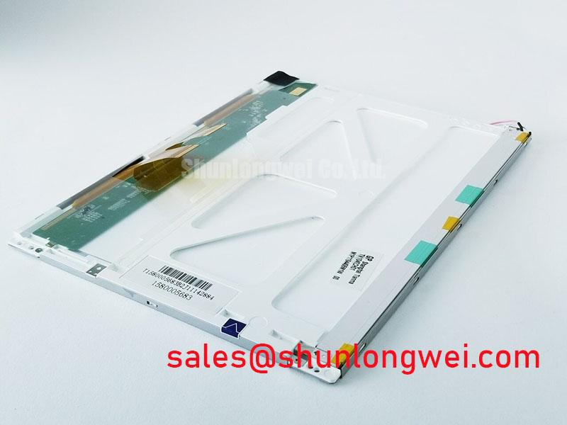
Check the panel connector orientation, mounting pressure, and backlight path before applying power to a replacement TM104SDH01-40. The unit is identified as a Tianma Industrial Grade LCD/HMI Panel using a TFT-LCD active matrix color display module in a standard form factor. Its decoded baseline is useful for maintenance planning, but connector pinout, supply voltage, timing, optical data, and backlight requirements must be matched with the original equipment documentation before installation.
For precision electronic test and measurement instruments, the display is part of a complete signal chain rather than an isolated visual accessory. Mechanical stress from a tight bezel, uneven gasket compression, cable movement, or thermal expansion can create intermittent symptoms that resemble a display electronics fault. Record the existing connector routing and panel seating position before removal, then compare the replacement against the removed unit without forcing the flexible cable into a sharper bend.
| Evaluation Item | TM104SDH01-40 | Reference Point |
|---|---|---|
| Manufacturer | Tianma | Industrial display manufacturer |
| Product category | Industrial Grade LCD/HMI Panel | LCD display module |
| Display construction | TFT-LCD active matrix color display module | Confirm optical and electrical compatibility |
| Form factor status | Decoded baseline and standard form factor | Verify bezel, mounting, and connector alignment |
Suppressing Acoustic Capacitor Buzz & EMI Emissions across 200 Hz to 1 kHz PWM Frequencies
When a test instrument produces audible noise during brightness control, begin by separating the display assembly from the cabinet power stage. A CCFL inverter may generate high-voltage cold-ignition conditions in the range specified by its own system design, while an LED solution uses a constant-current driver with its own switching and dimming behavior. These are different backlight architectures and must not be treated as interchangeable panel specifications.
The TM104SDH01-40 product identity supplied here does not assign a confirmed backlight type, ignition voltage, PWM range, or half-life rating. The system integrator should identify the original backlight driver and its control waveform before selecting a replacement driver. If brightness control is implemented through PWM, inspect the driver, wiring, and mechanical mounting together. Capacitor vibration, transformer activity, loose shields, and enclosure resonance can all contribute to audible output at low-frequency modulation.
Sub-zero operation adds a separate timing concern. Liquid-crystal response can become slower as ambient temperature falls, which may appear as elongated gray-to-gray transitions or motion smearing. A heater, if present in the equipment, belongs to the system thermal design and should not be assumed to be part of this display module. Use a controlled temperature test to compare startup behavior, image stability, and brightness regulation without assigning a field lifetime value that is not published for this exact configuration.
For enclosure work, keep the display sealing interface evenly supported and avoid concentrated pressure near the active area. A gasket that is compressed unevenly can distort the panel or create light leakage. ⚠️ Maintenance Note: Inspect the cabinet airflow path and sealing gasket during scheduled service, and disconnect power before removing the display cable.
Eye-Diagram Voltage Margin & Differential Noise Floor Verification in High-Vibration Bays
Pixel jitter and horizontal noise bands near variable-frequency motor drives should be investigated at the complete cable path, not at the LCD glass alone. First compare the known-good signal route with the replacement assembly, including cable length, connector insertion, shield termination, and the distance from motor output wiring. A shield that is bonded inconsistently at the panel and controller ends can allow common-mode interference to enter the display interface.
For an LVDS implementation, the controller documentation must define the differential pair assignment and electrical limits. A commonly used design reference is a controlled differential impedance of 100 Ω ± 10%, but this is a system routing consideration, not an official parameter assigned to the TM104SDH01-40 in the supplied product data. Pair skew should also be controlled by the system PCB and cable construction; the frequently used 50 ps design target requires validation against the actual transmitter, receiver, and cable specification.
In a high-vibration bay, inspect connector retention after thermal cycling and vibration exposure. A cable can remain visually connected while losing consistent contact pressure at the mating interface. The diagnostic sequence should compare eye opening, common-mode behavior, and ground reference stability at the controller output and panel input. If the noise appears only when a nearby drive changes speed, correlate the disturbance with the drive switching event and review cabinet bonding and cable segregation.
For compatibility research, TCG121XGLPCPNN-AN70 may be reviewed as a separate display reference, but a similar application category does not establish drop-in compatibility. Check active area, connector family, interface protocol, timing, mounting pattern, and backlight control before considering any substitution.
TTL 24-Bit Digital RGB Bus Synchronization & Logic Power Rail Verification
Split-screen images, incorrect colors, or unstable startup usually require a comparison of logic power sequencing and pixel-data mapping. The supplied baseline for TM104SDH01-40 does not confirm a TTL 24-bit RGB interface, a 3.3 V or 5.0 V logic rail, a specific rise-time window, or JEIDA/VESA mapping. These values must be taken from the original panel documentation and matched to the host controller rather than inferred from the model designation.
Where the instrument uses a parallel RGB bus, verify red, green, and blue bit order at the controller connector before changing firmware settings. A mapping mismatch can produce recognizable color errors without indicating physical damage to the display. Check pixel clock, horizontal and vertical timing, data-enable behavior, and reset sequencing with the panel disconnected first, then repeat the measurement at the panel input.
Power-on behavior should be assessed as a complete sequence. The controller, logic rail, reset signal, pixel clock, and backlight enable must reach their intended states in the order required by the original design. Any required rise-time interval belongs to the system integration requirements and must be validated using the controller and panel documentation rather than treated as confirmed factory data for this model.
PWM brightness control also requires separation between display logic and backlight electronics. A proposed 200 Hz to 1 kHz range can be evaluated as a system starting point when compatible with the driver, but it is not a confirmed specification for this Tianma module. Check duty-cycle linearity through the instrument’s normal brightness range and observe text edges, camera flicker, and audible behavior during the test.
The companion LQ104S1DG61 can be examined as a related display solution for system-level comparison. Its presence does not define the electrical interface of the TM104SDH01-40, so each panel requires independent connector and timing verification.
Constant Luminance Output Control & L70/B50 LED Half-Life Reliability Verification
Stable luminance depends on the display, backlight driver, thermal path, bezel pressure, and cabinet environment operating as one assembly. When a narrow display edge runs warmer than the opposite side, review the enclosure airflow, driver placement, conductive mounting surfaces, and cable routing before changing brightness settings. An aluminum spreader or other heat-spreading feature can be considered by the system designer, but its size and attachment method must be determined from measured thermal conditions.
The supplied product parameters do not provide an L70, B50, LED half-life, optical uniformity, or MTBF value for the TM104SDH01-40. Do not convert a generic industrial display lifetime claim into a guaranteed service-life figure for this exact assembly. Instead, record luminance uniformity, startup time, visible flicker, and panel temperature during representative operating cycles, then compare the results with the equipment acceptance criteria.
Mechanical installation deserves the same attention as electrical integration. Tightening a bezel unevenly can introduce localized stress, visible mura, or edge leakage. The gasket should sit flat around the full perimeter, while the flexible cable should remain supported without pulling on the connector latch. Thermal expansion between the chassis, bezel, and display frame should be allowed to settle through the mounting design rather than transferred into the active area.
Engineers assessing industrial HMI maintenance practices can consult Industrial Display & HMI Solutions for broader enclosure and integration context. For manufacturer-level display technology reference, review Tianma NLT Industrial TFT-LCD Display Technologies. The TM104SDH01-40 remains an industrial TFT-LCD display module whose final suitability depends on verified interface, mechanical, optical, and environmental compatibility with the precision instrument.