Content last revised on September 19, 2026
Assembly Integrity & Layout Architecture: Ensuring Uniform Heatsink Contact Pressure for TT500N16KOF
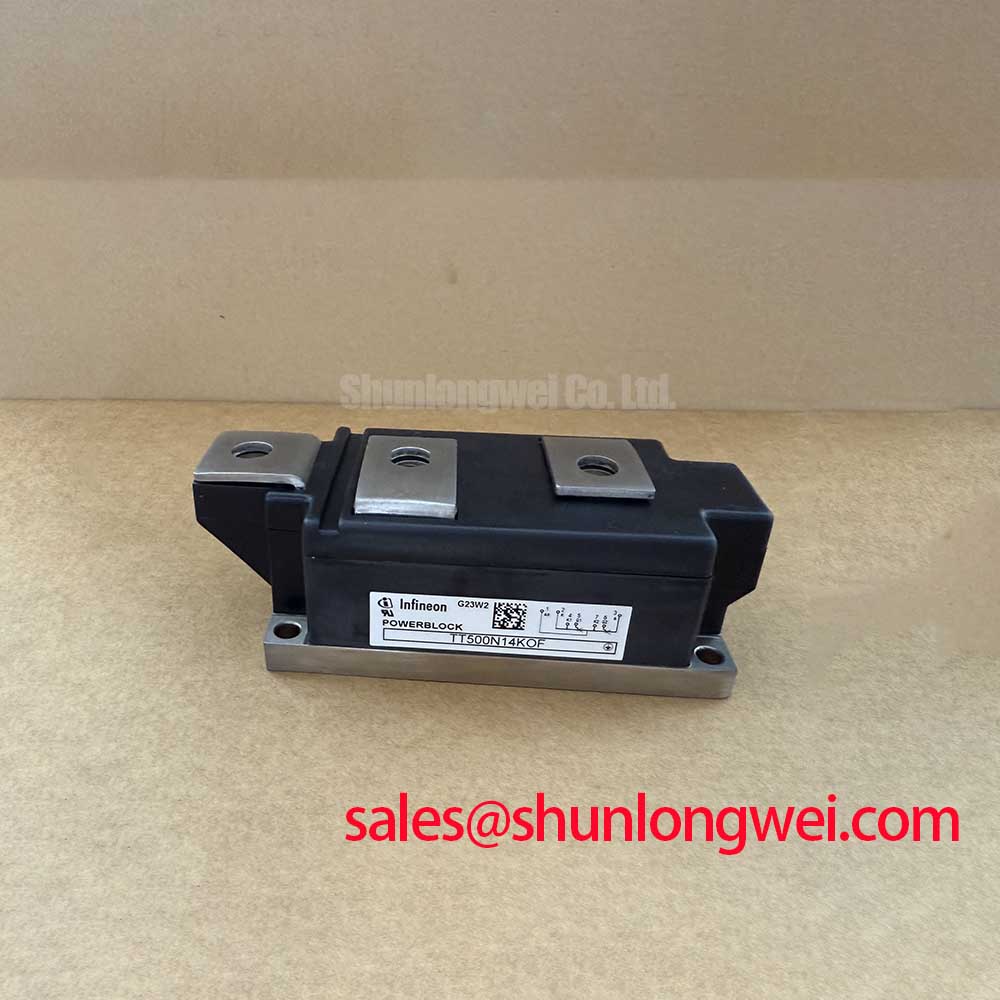
Begin maintenance by isolating the rectifier, confirming the nameplate boundary, and checking the module body, terminals, and copper mounting interface for visible damage or contamination. The TT500N16KOF is an Infineon Dual Thyristor Module rated at 1600 V and 500 A according to the supplied official product data, with a PowerBlock Module package.
For a high current green hydrogen electrolyzer DC power rectifier, the heatsink interface deserves the same attention as the electrical connections. The mounting surface should be clean, flat, and free from burrs. Apply the approved thermal interface material as a controlled, continuous layer, then tighten the fixing hardware progressively so that contact pressure develops evenly across the copper baseplate. The exact mounting torque, terminal torque, thermal resistance values, and permissible thermal cycling limits must be taken from the applicable Infineon mechanical and thermal documentation rather than estimated from package appearance.
Thermal inspection should compare the module baseplate, heatsink, and adjacent bus connections after the rectifier has reached a stable operating condition. A localized temperature difference may justify checking paste distribution, surface flatness, clamping sequence, airflow, and current sharing between parallel paths. The supplied product data confirms voltage and current ratings, but it does not establish a universal operating current for every cooling arrangement.
| Manufacturer | Infineon |
| Device category | Dual Thyristor Module |
| Voltage rating | 1600 V |
| Current rating | 500 A |
| Package | PowerBlock Module |
⚠️ Maintenance Note: Monitor contact temperature and clean the heatsink air path during scheduled service, especially where dust or moisture can reduce cooling performance.
Benchtop Waveform Tuning: Mitigating Stress via Dynamic Voltage Sharing and RC Damping in TT500N16KOF
Before energizing a replacement module, inspect the firing circuit, commutation path, fuses, busbar joints, and measurement connections. During a controlled bench test, oscilloscope probes should be connected with the shortest practical loop, and the observed voltage should be compared with the rectifier’s actual DC link conditions. Voltage sharing between thyristor paths is affected by circuit symmetry, stray inductance, recovery behavior, and the switching pattern of the complete converter.
RC snubbers are a Design Consideration, not an automatic TT500N16KOF specification. Their resistor, capacitor, pulse capability, and placement should be selected from measured overshoot, ringing frequency, leakage current, and thermal loading. A saturable reactor may also be evaluated where the system requires controlled current rise, but its suitability depends on the transformer, line impedance, firing angle, and fault-clearing strategy. Designers should verify the resulting peak voltage and current against the complete protection coordination study.
Fuse selection must use the applicable Infineon coordination information and the fuse manufacturer’s published I²t data. The module’s 1600 V and 500 A ratings do not by themselves define a suitable fuse, snubber, reactor, or overload profile. For semiconductor technology comparisons during a wider service review, engineers can consult Wide Bandgap Revolution while keeping the present thyristor module’s verified ratings separate from other device classes.
Benchtop Waveform Tuning: Mitigating Stress During High-di/dt Operation: Pulse-Train Timing on TT500N16KOF
Gate-drive checks should start with the original control schematic and the module terminal identification supplied for the specific assembly. Confirm trigger polarity, pulse isolation, wiring continuity, and the return path before applying repeated firing commands. A pulse-train strategy can be considered when the control system must maintain reliable triggering across changing line conditions, but pulse width, repetition, gate current, and gate holding behavior remain system-dependent unless explicitly stated in the manufacturer documentation.
High current rectifiers can show misleading firing behavior when the gate wiring shares impedance with power conductors or when the isolation stage is exposed to rapid common-mode transitions. Route the gate circuit away from high di/dt loops, verify the signal at the module terminals, and compare it with the controller output. If a waveform is unstable, review the optocoupler or digital isolator drive capability, isolation supply integrity, common-mode transient performance, and grounding arrangement. Infineon’s information on automotive qualified power modules and intelligent power modules provides broader manufacturer context, but it does not replace the TT500N16KOF gate-drive documentation.
TT500N16KOF Circuit Protection & Reliability: Calibrating AC Line Surge Immunity and Lightning Transients
AC input protection should be reviewed from the upstream transformer and switchgear toward the thyristor bridge. MOVs, fuses, line reactors, RC suppression, and surge coordination must be selected from the installation’s prospective short-circuit current, transient environment, grounding system, and applicable compliance test plan. IEEE 61000-4-5 testing can guide system-level evaluation, but passing a surge test for the complete rectifier cannot be attributed to the module alone.
For an electrolyzer DC power rectifier, record line voltage, firing angle, DC output ripple, commutation notches, and peak semiconductor voltage during representative load transitions. Phase-controlled operation can increase input harmonics, so the filter and power-factor strategy should be assessed with the complete transformer and converter topology. Regenerative braking choppers and braking resistors belong to a different energy path; they should not be assumed to protect this dual thyristor module unless the circuit architecture explicitly connects them.
Where the equipment operates at altitude or in areas exposed to lightning activity, insulation coordination, creepage, clearance, cooling performance, and surge withstand require application-specific verification. No FIT rate, single-event burnout limit, cosmic-ray withstand value, or service-life figure is established by the supplied product parameters. Maintain test records for terminal condition, thermal behavior, gate waveform, protection response, and fuse coordination so that future replacement decisions remain tied to measured equipment conditions.