Content last revised on October 6, 2026
TX18D45VM5BPA KOE Hitachi Industrial LCD Display Module
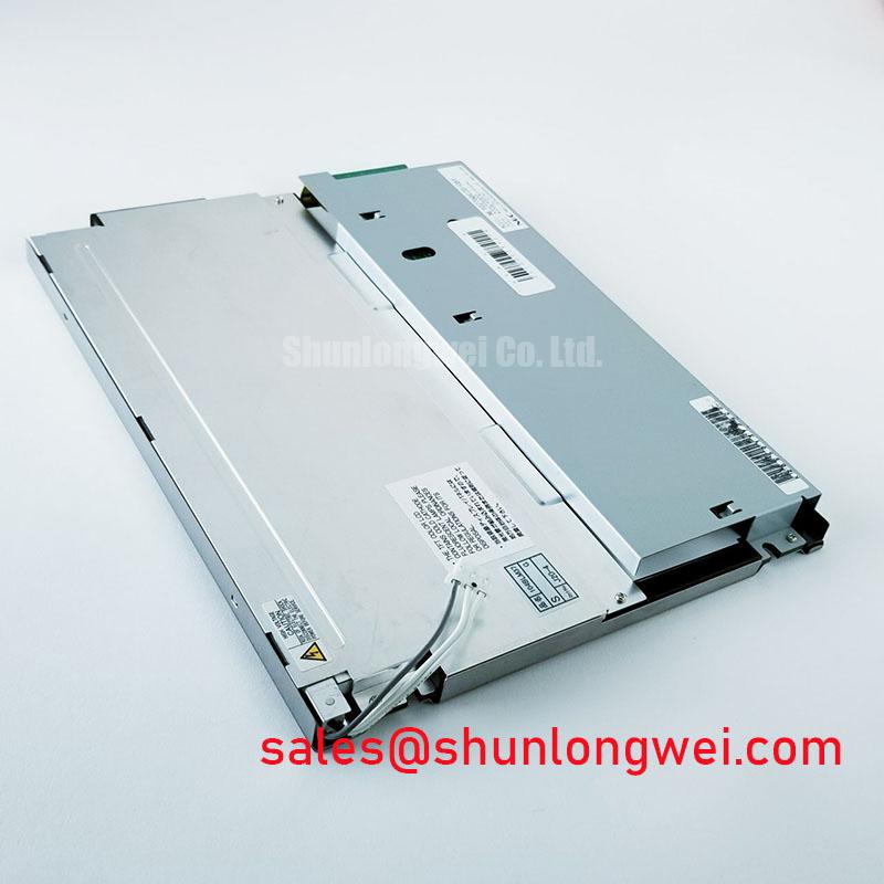
Begin a replacement inspection by comparing the panel label, connector orientation, mounting points, and enclosure opening with the removed display before applying power. The TX18D45VM5BPA is identified in the supplied factory information as a KOE / Hitachi TFT LCD Display Module for industrial LCD and HMI applications. Its available classification is Industrial Grade LCD/HMI Panel, with an official factory specification status provided for the product record.
Because the supplied product data does not confirm the interface pinout, logic supply voltage, backlight architecture, optical performance, or mechanical drawing, those items must be checked against the original panel documentation and the equipment service manual. This distinction matters when evaluating the unit for a railway passenger information system, cab signalling display, industrial controller, or another HMI assembly.
| Item | Available product information |
|---|---|
| Model | TX18D45VM5BPA |
| Manufacturer | KOE / Hitachi |
| Product category | Industrial Grade LCD/HMI Panel |
| Construction category | TFT LCD Display Module |
| Specification status | Official Factory Spec Verified |
| Interface and electrical data | Verify from the original panel documentation before integration |
Display Interface Synchronization and Logic Power Rail Verification
The first electrical task is to identify the actual signal interface fitted to the target equipment. The model record supplied here does not confirm whether the host uses a TTL digital RGB bus, LVDS, or another display link, so the system integrator should verify the connector pinout, signal naming, logic supply requirement, backlight enable line, and brightness control method from the original panel documentation. A connector that appears mechanically compatible may still use a different data mapping or power arrangement.
For equipment using a TTL 24 bit RGB architecture, the service check should cover red, green, and blue data groups together with the pixel clock, horizontal synchronisation, vertical synchronisation, and data enable signals where applicable. If the interface is LVDS, JEIDA and VESA bit mappings are not interchangeable assumptions. A mapping error can produce abnormal colour channels, split images, incorrect grayscale progression, or a display that appears active but does not reproduce the source image correctly. The replacement should therefore be checked against a known good controller or the original display before final installation.
Power sequencing also requires system-level verification. The required logic rail voltage, permitted rise time, reset behaviour, and enable order are not stated in the available factory data for this product record. Designers should measure the host board during startup and compare the result with the original panel documentation rather than applying a presumed 3.3 V or 5.0 V supply. The same principle applies to backlight enable and dimming pins, which should remain unconnected until their electrical function has been confirmed.
Where a high-speed differential link is used elsewhere in the equipment, the board designer should control the signal return path, maintain consistent routing geometry, and verify characteristic impedance according to the transmitter, cable, and receiver requirements. These are Design Considerations, not confirmed factory specifications for the TX18D45VM5BPA. An oscilloscope or suitable protocol test method can help compare clock quality, data timing, and image stability between the removed panel and the replacement assembly.
For a same-class display comparison, engineers may review TX20D200VM2BVA as a separate reference product. It should not be treated as a direct substitute unless the active area, resolution, connector, mounting geometry, timing parameters, optical requirements, and backlight system have all been matched.
Ambient light performance also needs measurement rather than assumption. Contrast ratio, anti-glare treatment, luminance, and viewing-angle behaviour are not confirmed in the supplied specifications. If the display is considered for a railway passenger information system or cab signalling interface, test the assembled screen through the actual front window, bezel, and cover material under representative illumination. The enclosure and cover can change reflections and perceived contrast even when the source panel is unchanged.
Single Vertical Hairline Defect and Sub Pixel Column Driver Open Circuit Localization
A narrow vertical line should be investigated with the panel connected to a known-good signal source and with several uniform test images displayed. A practical sequence is to check a white field, a black field, and primary red, green, and blue fields. Record whether the line remains fixed in the same physical location, changes with image content, or disappears when the display cable and controller are inspected. This procedure helps separate a panel-side visual defect from a signal path or processing fault without assigning a single cause prematurely.
A dark-room flashlight inspection can add useful information. Holding a light source at an oblique angle across the front surface may reveal whether the apparent line is related to surface contamination, cover reflection, or an area of nonuniform illumination. The test should be performed without pressing the active area. Mechanical pressure can change the appearance of liquid crystal cells and may obscure the original fault condition.
If the line remains fixed during primary-colour testing while the source timing remains stable, the engineer may need to compare the affected column position with the panel connection and driver region described in the original service documentation. A suspected open circuit or driver interconnect issue should be verified through controlled comparison, not inferred from one image alone. The supplied factory information does not provide a field failure rate, repair threshold, or internal driver construction for this model.
Cold-temperature operation introduces another diagnostic variable. Liquid crystal response can become slower as the panel temperature falls, and the displayed image may show visible transition lag or altered grayscale behaviour. The permissible operating temperature range for the TX18D45VM5BPA is not included in the available product record, so the system engineer should obtain that value from the panel datasheet before evaluating operation below room temperature. A heater strip, if used in the host equipment, must be controlled from the enclosure thermal design rather than connected directly to an unverified panel circuit.
For railway or outdoor HMI evaluation, test the complete assembly rather than the bare panel only. The bezel, window, sealing method, cable bend radius, and local heat sources can influence condensation, optical uniformity, and startup behaviour. The engineering guide Industrial Display and HMI Solutions provides additional system-level context for evaluating display integration in demanding enclosures.
High Voltage Striking Potential and Secondary Coil Insulation Testing
Backlight identification must precede any electrical test. The supplied data classifies the unit as a TFT LCD Display Module but does not confirm whether the original assembly uses a CCFL backlight, an LED backlight, an integrated inverter, or an external driver. The system integrator should verify the backlight technology and connector definition from the original panel documentation. Applying a high-voltage ignition test to an unverified connector can damage the panel, the driver, or the measuring instrument.
For a documented CCFL configuration, the inverter secondary circuit should be assessed with equipment rated for the expected high-voltage waveform and insulation environment. The relevant striking voltage, operating voltage, current, insulation distance, and test method must come from the applicable panel and inverter documents. They are not official TX18D45VM5BPA values in the supplied specification set. Acoustic noise, intermittent ignition, and uneven brightness should be checked at the complete assembly level because the inverter, lamp, cable routing, chassis, and enclosure can all influence the result.
For a documented LED configuration, the replacement driver must be matched to the LED string arrangement, current regulation method, enable logic, and dimming input. PWM dimming behaviour should be assessed for visible flicker, camera banding, and brightness linearity under the actual host controller. A claimed dimming ratio or operating frequency should not be assigned to this panel without a source in the original documentation.
High-speed signal integrity remains relevant when the display uses a serial interface or an external transmitter board. Clock jitter, setup and hold timing, cable routing, and ground reference should be compared across the intended industrial temperature window. The correct acceptance limits are system-dependent and should be taken from the transmitter and receiver specifications. An oscilloscope check at the panel connector is more useful than relying on a visually stable image at one temperature.
There is no source in the supplied product information for a guaranteed half-life, MTBF value, insulation certification, or independent EMC certification. Such claims should not be attached to the TX18D45VM5BPA without an applicable manufacturer document or recognised test report. The display module is one part of the equipment; the finished railway display or HMI must be evaluated as a complete system for electrical safety, EMC, thermal behaviour, and enclosure protection.
💡 Pro Tip: Keep the display cable reference plane continuous and verify differential pair symmetry or TTL return paths at the controller and panel connectors before changing software timing.
Grayscale Inversion Mitigation and Viewing Direction Alignment
The optical structure of the TX18D45VM5BPA is not fully described in the available factory information, so its panel mode, viewing direction, contrast ratio, grayscale response, and surface treatment should be confirmed before a mechanical redesign. Do not assume that a replacement display has the same viewing cone or grayscale behaviour as an IPS or MVA panel. A viewing-angle difference can become noticeable when a cab display is viewed from below, above, or from an offset operator position.
If the installed panel is a normally white TN type, grayscale inversion may appear when the observer moves away from the preferred viewing direction. The appropriate mitigation is usually mechanical alignment, interface placement, and selection of a panel with optical characteristics suitable for the actual viewing position. This is a Design Consideration, not a confirmed characteristic of the model. Compare grayscale test patterns from the intended operator angle and document the acceptable image orientation before fixing the bezel.
Anti-glare performance should be judged with the final cover, window, and illumination environment in place. Surface etching, anti-glare films, optical bonding, and cover glass can change haze, reflections, touch response, and perceived sharpness. The supplied information does not confirm that the TX18D45VM5BPA includes optical bonding, a specific anti-glare coating, or a sealed front construction. These features must be verified from the mechanical and optical documentation or inspected against the original assembly.
Backlight uniformity also depends on the complete stack-up. Designers should inspect the light-emitting area, diffuser condition, panel frame, thermal path, and nearby heat sources when evaluating local brightness variation or hot spots. A replacement should be tested after enclosure assembly because a bare-panel result may not represent the thermal and optical conditions inside a signalling display or passenger information terminal.
The panel mounting aperture, connector clearance, cable exit direction, and front-surface position should be checked against the equipment drawing before procurement approval. For comparison with another display assembly, engineers can review LM190E08-TLG6, while keeping the display and driver compatibility review separate. Final acceptance should be based on verified electrical, optical, mechanical, and environmental data for the complete assembly.