

Content last revised on October 16, 2026
Flush-Mount Open-Frame Bezel Integration & Perimeter Gasket Shock Isolation
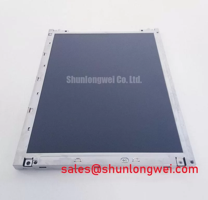
Check the enclosure opening against the panel drawing before tightening the mounting hardware. As a Design Consideration, the bezel should clear the active image and accommodate assembly tolerances without pressing against the viewing surface. Locate support at the designated mounting features, and check cable clearance with the enclosure fully closed, including the space occupied by connector housings and strain relief.
A perimeter gasket should distribute enclosure contact without transferring concentrated pressure into the display. Select its compression behavior from the enclosure stack and gasket supplier’s data. During trial assembly, compare a dark image and a uniform gray image before and after fastening. Changes in shading can help identify mounting stress, but require comparison with the unloaded panel before assigning a cause. Fastener size and tightening torque belong to the approved mechanical drawing.
For optical bonding, assess adhesive compatibility, differential expansion, rework requirements, and the load transferred through the cover glass. Bonding can reduce internal reflections, but enclosure sealing remains a separate design task. Sunlight readability requires an assembled optical assessment under representative illumination; neither an anti-glare surface nor a contrast value measured under different conditions establishes outdoor visibility.
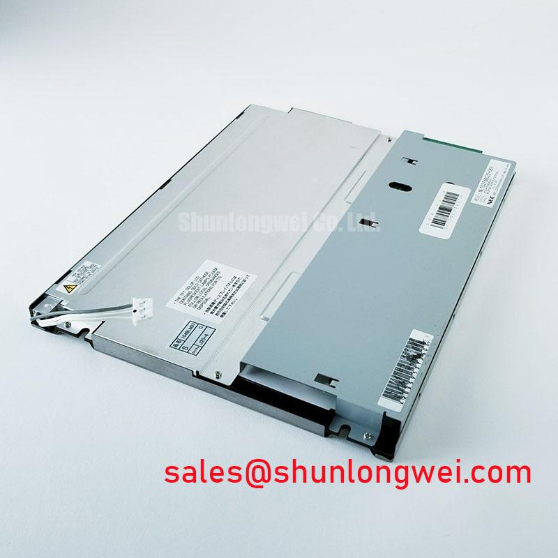
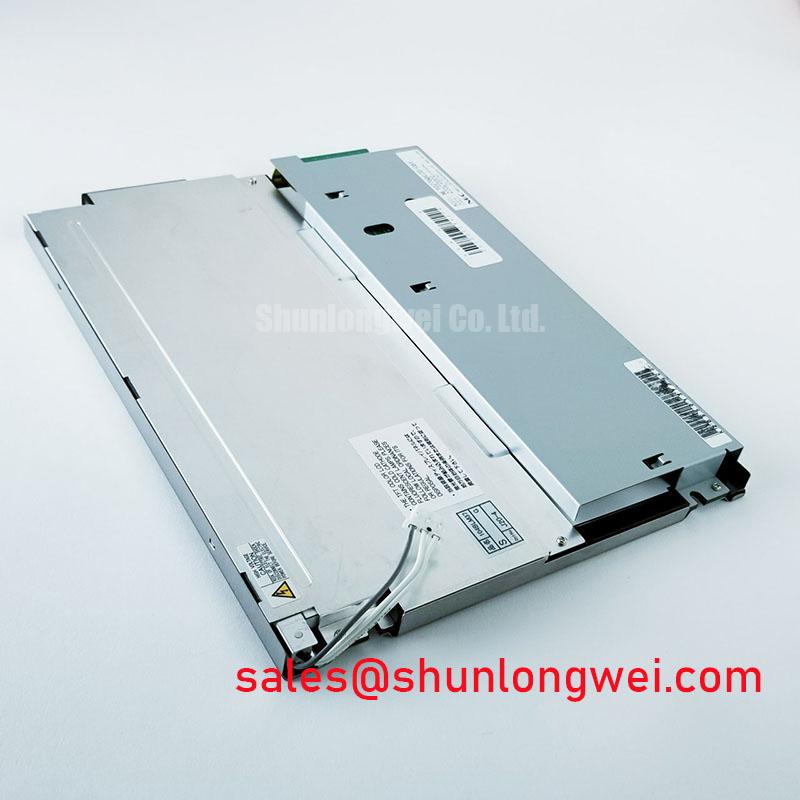
When evaluating an AGV or forklift telematics display, designers should assess enclosure vibration, viewing position, cable retention, and environmental sealing at system level. The NL8060BC31-42 can be included in a broader NEC display comparison, with resolution, dimensions, optics, and interface checked independently before any substitution decision.
Full-Screen Primary Color AOI Screening: Stuck Sub-Pixels & Background Uniformity Audit
Display full-screen red, green, and blue images through a controller configured for the panel’s documented native timing. As an Engineering Recommendation, inspect each image from a fixed position and record persistent bright or dark subpixels by location. Follow with white, black, and gray patterns to distinguish color-channel behavior from background nonuniformity. Apply the manufacturer’s applicable acceptance criteria rather than inventing a universal defect allowance.
If the screen appears dark, oblique external illumination can help establish whether a faint image remains present. That observation supports separate checks of the image path and illumination system; it does not identify a failed part by itself. Compare controller output, panel supply behavior, backlight control, and connector seating with a known working assembly. Avoid pressing the glass or flexing the panel to investigate intermittent lines.
Before evaluating signal integrity, establish the exact interface and connector pin assignment. For an LVDS implementation, compare transmitter mapping, receiver requirements, and clock relationships; JEIDA/VESA alignment must follow the actual interface documentation. For a parallel interface, compare clock polarity and setup and hold requirements at the receiving connector. Evaluate timing across the intended operating conditions rather than assigning a generic jitter margin.
Engineering Recommendation: Match differential routing and preserve a continuous return path where the documented interface uses differential pairs, then verify signal quality at the receiver. Check startup and shutdown waveforms against the specified sequencing relationships. A white screen or retained image during a transition warrants examination of supply stability, valid data, and backlight timing together.
For static HMI graphics, consider screen blanking, modest content movement, or changing inactive content where the machine interface permits. These are Design Considerations for reducing prolonged static drive patterns. Persistent marks should be assessed using controlled test content and recovery observations before classifying the condition as permanent damage.
Aluminum Heat Spreader Sizing & Thermal Interface Placement along Narrow Display Edges
Map enclosure and panel surface temperatures during representative operation before selecting an aluminum spreader. As a Design Consideration, a spreader should connect an identified heat source to a useful chassis dissipation path without applying load to the glass or obstructing connectors. Its dimensions depend on measured heat distribution, enclosure airflow, mounting geometry, and allowable temperatures.
Place thermal interface material only on mechanically supported surfaces suitable for contact. Check electrical clearance, material migration, and assembly compression before closing the enclosure. An edge rail that improves heat transfer can also alter panel loading, so repeat the uniformity inspection after thermal stabilization. Do not infer internal optical materials, LED lifetime metrics, or a permissible edge temperature from the presence of a metal frame.
Evaluate the backlight power circuit separately from the image interface. Match its supply, enable behavior, and brightness control to the documented illumination assembly. Constant-current dimming is relevant only when supported by the actual backlight architecture. The NL8060BC21-09 is another display module for system comparison, rather than a backlight driver; its supporting circuitry requires its own compatibility assessment.
Temperature testing should also include grayscale transitions, color appearance, and viewing direction at the installed angle. IPS or MVA behavior should not be attributed to this model without a confirmed optical specification. Tianma’s industrial TFT display solutions information provides broader display context; model-specific optical limits govern the actual integration.
Radiated Emissions Compliance (CISPR Class A/B) via Backplate Multi-Point Star Grounding
Inspect the cable shield termination and chassis bonding arrangement before adding suppression components. As a Design Consideration, high-frequency return paths depend on connection geometry and impedance; a star arrangement or multiple backplate contacts cannot establish emissions compliance by itself. Select the bonding scheme through enclosure measurements and the applicable equipment test plan. CISPR classification belongs to the tested equipment configuration.
Where a shielded display cable is specified, maintain its shielding through the connector and chassis transition. Consider common-mode suppression only after measurements identify the coupling path, then check its effect on image integrity. Noise bands or pixel instability near motor-drive wiring can have several causes, including supply disturbance, signal degradation, and grounding interactions. Correlate symptoms with measured disturbances before changing hardware.
For cold operation, assess image response and startup within the panel’s documented temperature limits. Slower liquid-crystal response is a temperature-dependent design consideration, not evidence of a particular low-temperature rating. Any enclosure heater requires separate control, temperature sensing, and condensation assessment. The The Ultimate Guide to Industrial TFT LCD Technology provides supporting integration context; finish the equipment evaluation with repeatable image, sequencing, and emissions checks in the assembled enclosure.