




Content last revised on September 22, 2026
Infineon TZ600N16KOF Specifications and Application Review
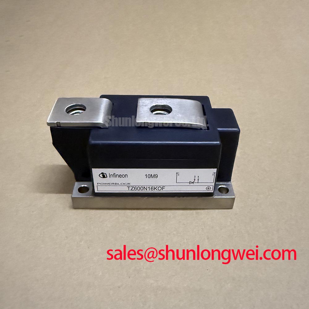
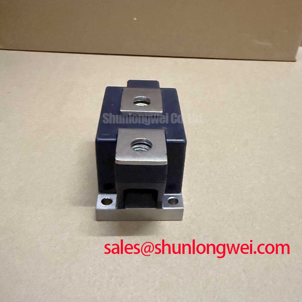
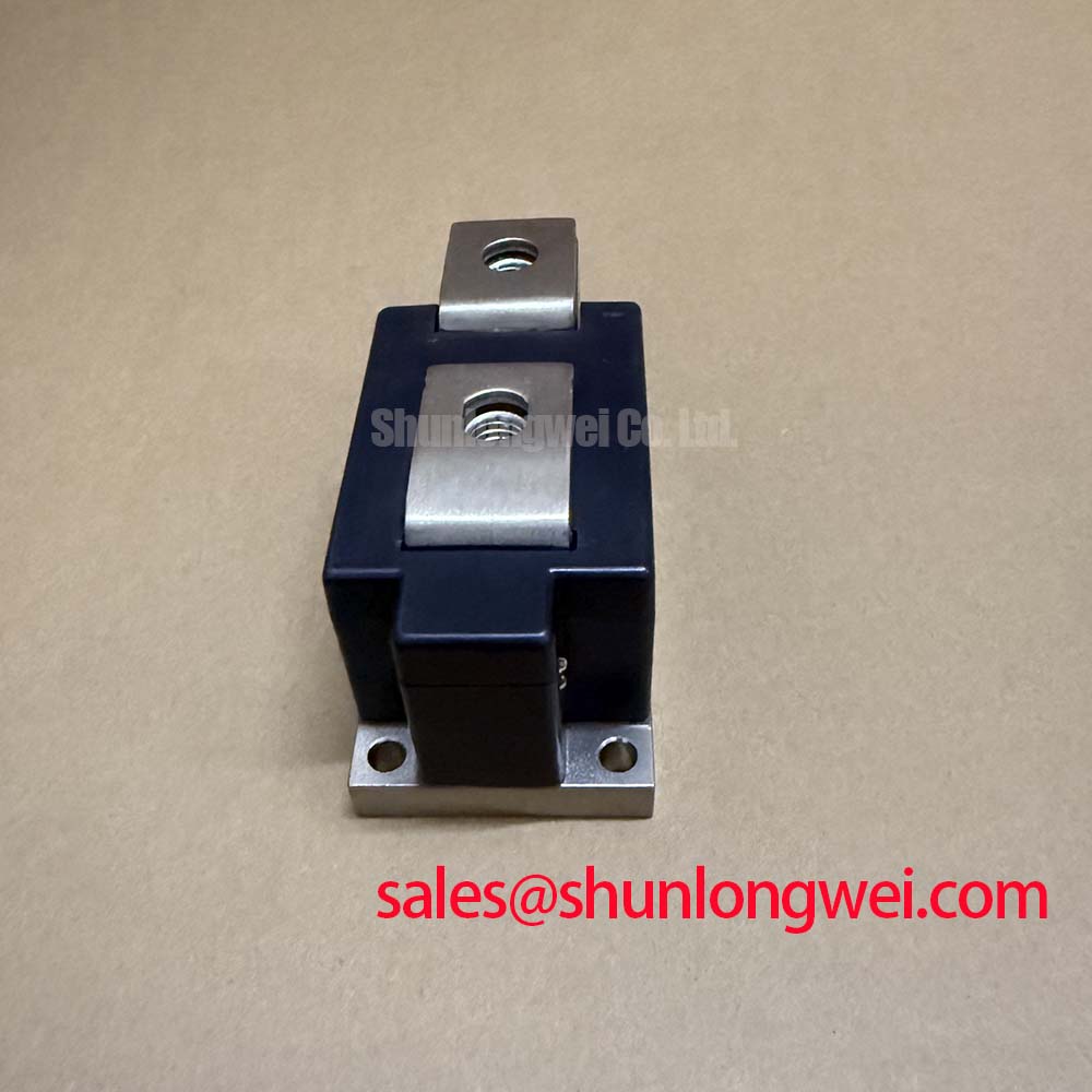
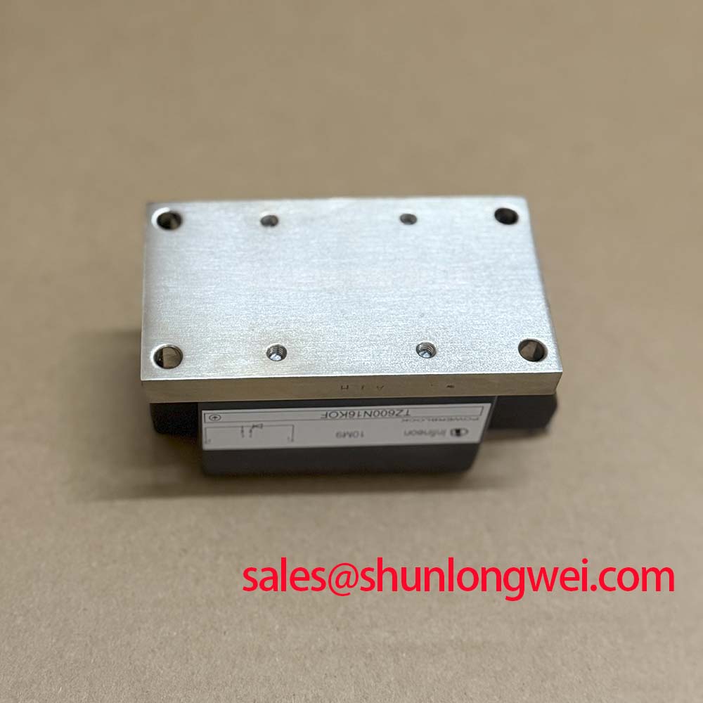
Verify the nameplate, terminal identification, and cold electrical condition of the Infineon TZ600N16KOF before connecting it to a high voltage three phase motor soft starter. The module carries an official repetitive peak off state voltage rating of 1600 V, a surge current rating of 17000 A at 10 ms and Tvj = 135°C, and a junction to case thermal resistance of 0.065 K/W per thyristor. Its official isolating voltage is 4000 V RMS at 50 Hz.
| Parameter | Official specification | Integration relevance |
|---|---|---|
| Repetitive peak off state voltage | 1600 V | Check the complete line and transient environment before applying this rating to 400 V, 480 V, or 690 V AC equipment |
| Surge current | 17000 A at 10 ms, Tvj = 135°C | Relevant to short duration inrush and fault coordination evaluation |
| Junction to case thermal resistance | 0.065 K/W per thyristor | Use when evaluating heatsink contact, thermal interface quality, and junction temperature margin |
| Isolating voltage | 4000 V RMS at 50 Hz | Supports insulation coordination review between the terminals and isolated baseplate |
Benchtop Waveform Tuning: Current Limit Mode Versus Linear Voltage Ramp
Begin the soft starter evaluation with the motor disconnected or with a controlled test load, then confirm gate trigger timing, phase sequence, and the measured line current on every phase. Current limit mode and linear voltage ramp produce different motor acceleration profiles. The correct setting depends on motor locked rotor characteristics, load torque, bypass contactor timing, and the upstream protection scheme; neither control method should be treated as a fixed property of the TZ600N16KOF.
The 1600 V VDRM rating defines an important off state voltage boundary, while the 17000 A surge current specification is a short duration device rating rather than permission to operate continuously at fault current. During waveform tuning, capture the applied voltage and current at the thyristor terminals and compare the peak values with the complete system protection study. Fuse coordination must use the manufacturer’s approved fuse I²t data and the module’s applicable withstand information. The supplied product data does not establish a universal fuse size or clearing time.
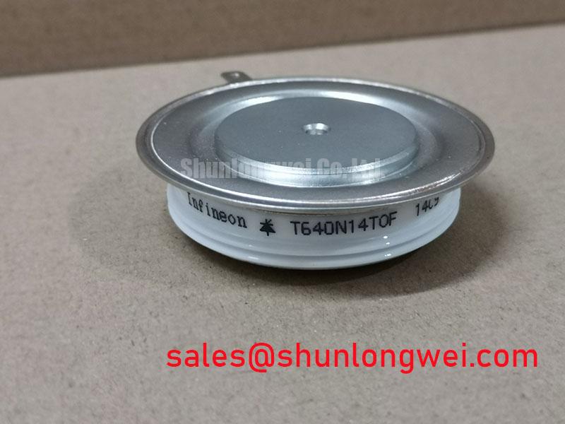
For field replacement work, engineers can evaluate the related TT570N16 as a separate compatibility candidate, but the electrical rating, gate requirements, package arrangement, and mechanical interface must be checked against the original assembly before substitution.
Assembly Integrity and Layout Architecture: Applying Baseplate Thermal Resistance
The official 0.065 K/W per thyristor Rth(j-c) value is meaningful only when the mounting surface, thermal interface, and clamping arrangement provide a consistent heat path. Inspect the heatsink for flatness and contamination, apply the interface material according to its manufacturer’s process instructions, and tighten the mounting hardware using the original device documentation. The module should sit evenly on the heatsink without mechanical distortion.
Keep the high current paths short and symmetrical where practical. The gate wiring should be routed away from high di/dt power conductors, with the return path controlled by the actual gate circuit topology. Designers should verify gate trigger amplitude, pulse duration, noise immunity, and common mode behavior at the installed drive board rather than inferring them from the module voltage rating.
Safety interlock note: Isolate and discharge the equipment before removing terminals or changing gate wiring, because the 4000 V RMS isolation rating does not make an energized assembly safe to touch.
When the module is used beside a rectifier stage, the TD210N12 may be reviewed as a neutral reference for system topology planning; it is not a blanket replacement recommendation for any circuit position. For package and thermal architecture comparisons, engineers may also consult Infineon’s PrimePACK™ and EconoDUAL™ 3 platform information, while recognizing that those product families do not define the TZ600N16KOF specification.
Transient Dynamics and Electrical Design: I²t Protection Coordination
A semiconductor fuse study should compare the fuse clearing energy with the thyristor’s applicable surge and fault withstand data under the actual prospective short circuit. The 17000 A at 10 ms official surge specification is a defined test condition, not a complete short circuit protection design. Fuse selection also depends on line impedance, available fault current, ambient temperature, repetitive duty, and the physical placement of the protective device.
During commissioning, record the voltage across the module, phase current, gate command, and fuse interruption behavior. Review the oscilloscope record for excessive commutation overshoot or unintended retriggering. Minimize parasitic inductance in the power loop to reduce transient stress, then verify the resulting peak voltage against the applicable device voltage ratings and the system’s design margin during switching tests. The exact electrical margin remains system determined.
For detailed gate circuit review and bench test planning, the Precision Gate Drive Design reference can be used alongside the applicable Infineon documentation. No FIT rate, service life, altitude derating value, or single event burnout limit is established here without a qualified source for the exact device and operating conditions.
TZ600N16KOF Operational Boundaries: Reverse Recovery and Commutation Review
The provided official parameter set identifies the TZ600N16KOF as a high voltage thyristor and diode module but does not specify diode reverse recovery charge, reverse recovery time, or reverse recovery peak current. Those values must be taken from the applicable manufacturer datasheet or lot specific documentation before making a switching loss or EMI calculation. Do not infer them from the 1600 V rating, the surge current value, or the thermal resistance.
For a three phase soft starter, inspect commutation at the actual line frequency, motor current, load power factor, and bypass transition point. A current probe and differential voltage probe can reveal abnormal overlap, ringing, or failed turn off, but the waveform should be compared with a known good system condition rather than assigned a single diagnostic cause. Gate drive isolation, common mode transient immunity, cable routing, and controller timing should be validated together.
Where the application requires fast repetitive switching rather than line frequency phase control, the system designer should confirm that the device family and its published dynamic ratings match the topology. Any EMC assessment belongs to the complete assembly and installation; the module itself should not be represented as independently certified to a system level EMC standard.