

Content last revised on October 19, 2026
TT570N16KOF08C11 Circuit Protection & Reliability: Calibrating RC Snubber Network Optimization
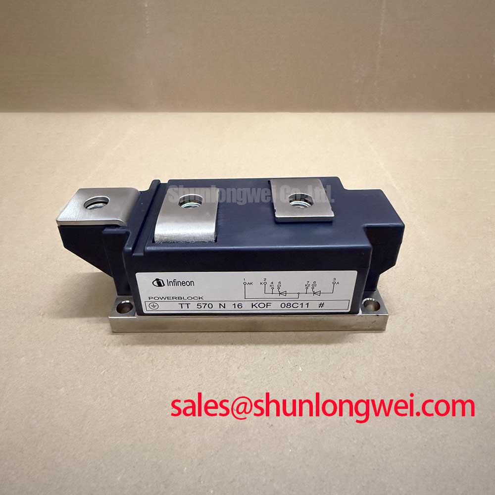
With the power circuit isolated and stored energy discharged, trace the main terminals and gate returns against the equipment schematic before reconnecting the TT570N16KOF08C11. This Infineon dual thyristor module has an official repetitive peak off-state and reverse voltage rating of 1600 V and an average on-state current rating of 570 A at a case temperature of 85°C. Preserve those test conditions when comparing the module with the original equipment requirements.
The remaining official specifications establish separate operating boundaries: 900 A RMS on-state current, 13500 A non-repetitive surge current for 10 ms at a junction temperature of 25°C, and a typical on-state voltage of 1.69 V at 1500 A and 125°C junction temperature. Junction-to-case thermal resistance is 0.040 K/W, while maximum gate trigger current is 200 mA. The typical voltage drop describes its stated measurement point; it does not provide a complete conduction-loss curve.
Measure the anode-to-cathode voltage during blocking and commutation before adjusting the RC snubber. As a Design Consideration, select snubber resistance and capacitance around the observed voltage rise, ringing, resistor dissipation, and capacitor pulse loading. Validate the resulting waveform across the equipment’s operating conditions rather than assigning component values from the module’s voltage rating alone.
A series saturable reactor requires a separate assessment of current rise during turn-on, magnetic reset, and saturation behavior. As a Design Consideration, excessive current rise can concentrate conduction before the conducting region spreads through a thyristor. Reactor selection therefore belongs with the measured firing waveform and the manufacturer’s permissible current-rise characteristics. Snubber changes also alter discharge current at firing, so evaluate their interaction.
For fuse coordination, compare the semiconductor fuse’s total clearing I²t at the prospective fault current with the module’s applicable surge withstand data under matching conditions. Include operating temperature and voltage recovery in that comparison. The 13500 A surge rating alone does not establish fuse compatibility or guarantee containment during a short circuit. Assembly checks should cover terminal orientation, specified fastening torque, heatsink contact, and the thermal interface using the applicable mechanical drawing.
Engineering Recommendation: Keep the power connection loop compact and mechanically balanced to limit inductive voltage excursions, then verify the peak terminal voltage during representative switching tests.
Benchtop Waveform Tuning: Assessing Non-Repetitive Surge On-State Current Stress on TT570N16KOF08C11
Capture the complete current pulse and the voltage that follows it when assessing the 13500 A, 10 ms surge boundary. Its 25°C initial junction temperature matters: a warm module cannot be evaluated by treating the cold surge value as a repetitive operating allowance. For sinusoidal half-cycle assessment, compare pulse duration, waveform shape, and subsequent reverse-voltage conditions with the applicable manufacturer test conditions.
The 0.040 K/W junction-to-case thermal resistance supports steady thermal assessment; short surge events require transient thermal information. As a Design Consideration, assess initial temperature, pulse energy, and recovery intervals together before repeating a test. Record case temperature at a defined location and preserve the mounting arrangement so that successive waveform comparisons remain meaningful.
When evaluating compatibility with a high-voltage three-phase motor solid-state soft starter, check the actual voltage imposed on each thyristor, its conduction duty, and the cooling arrangement. The TT330N16KOF12M1 comparison provides an additional sourcing reference, but replacement qualification requires matching circuit configuration, terminal geometry, thermal performance, and protection coordination. A shared voltage class does not establish interchangeability.
Engineers consulting The Ultimate IGBT Knowledge Base for switching-test context should retain the distinction between transistor switching and thyristor commutation when evaluating stress margins.
Preventing Spurious Faults: Gate Trigger Current Dynamics Guidelines for TT570N16KOF08C11
Measure gate current at the module connection together with anode current to establish whether the firing pulse persists until conduction becomes self-sustaining. The 200 mA maximum gate trigger current is an official trigger characteristic, not a complete prescription for pulse amplitude, rise time, duration, or gate power. As a Design Consideration, establish these settings against the permitted gate characteristics and actual load-current buildup.
A sustained pulse tail or a pulse train can support firing when current builds slowly, provided the gate’s pulse and average loading limits are respected. Holding current describes continued main-current conduction after latching; it is distinct from gate trigger current. Keep the gate and its cathode return closely routed, and compare their waveforms during disturbed and stable operation before attributing intermittent conduction to the module.
When reviewing associated power stages, assess TT425N18KOF against its own circuit role and firing requirements. Infineon’s OptiMOS low-voltage MOSFET and EconoPACK Plus IGBT references concern different device technologies. For this thyristor, diagnose unintended firing through gate coupling, blocking-voltage rise, and commutation measurements rather than applying transistor Miller-clamp settings or freewheeling-diode recovery assumptions.