
Content last revised on September 21, 2026
Assembly Integrity & Layout Architecture: Implementing AC Line Surge Immunity and Lightning Transients for VSKH91/12P
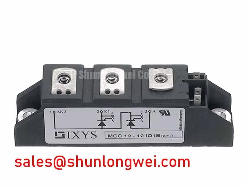
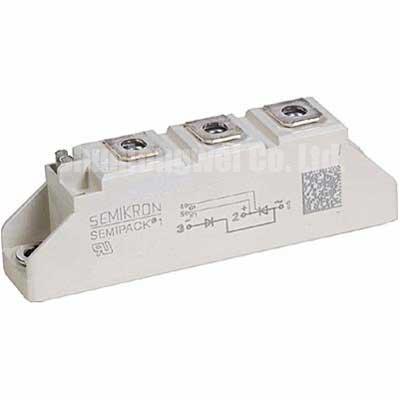
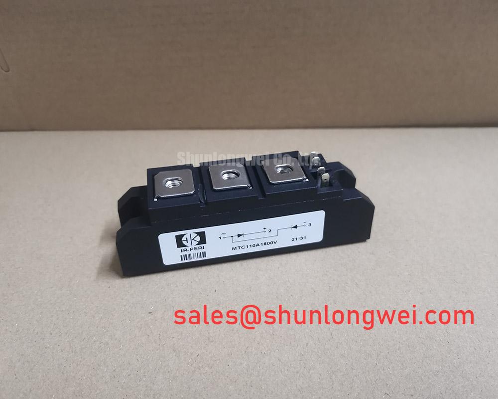
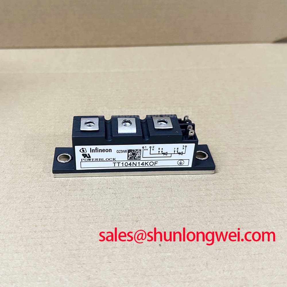
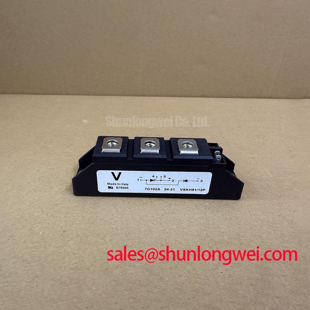
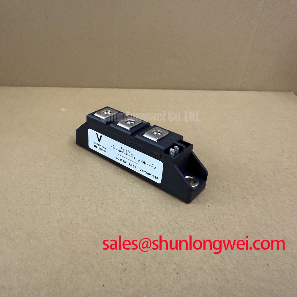
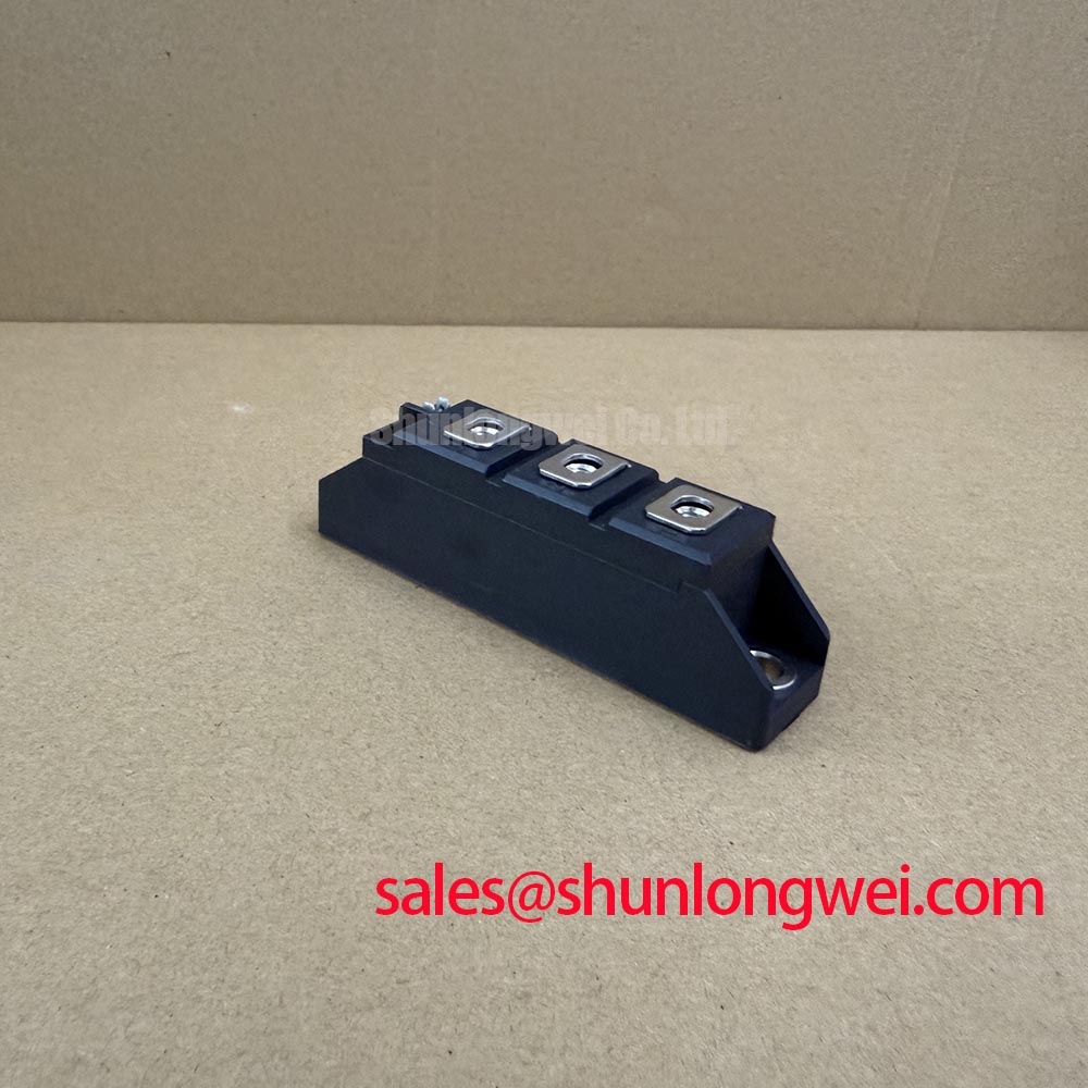
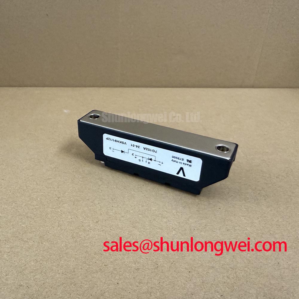
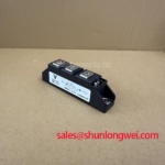
Before connecting a replacement module, use a diode-test meter to compare the cold-state conduction paths at the marked power terminals with the circuit symbol and original equipment documentation; this verifies terminal polarity without applying line voltage to the Vishay VSKH91/12P. This thyristor/diode module is rated at 1200 V maximum repetitive peak reverse voltage and 95 A average forward current under specified datasheet conditions. Its ADD-A-PAK Gen 7, TO-240AA package provides the mechanical and thermal interface that must be matched to the existing heatsink, busbar arrangement, insulation parts, and terminal hardware.
The 2094 A non-repetitive surge-current rating at 50 Hz, under the specified datasheet conditions, is an Official Datasheet Specification relevant to short-duration fault and inrush conditions. It is not a continuous operating-current rating or a substitute for correctly coordinated semiconductor fusing. For a high-voltage three-phase motor solid-state soft starter, the module should be evaluated in the actual phase-leg topology, including the firing circuit, line protection, load current profile, cooling path, and commutation conditions.
| Official specification | Value | Integration relevance |
|---|---|---|
| Maximum repetitive peak reverse voltage, VRRM | 1200 V | Defines the repetitive reverse-voltage boundary under the specified conditions. |
| Average forward current, IT(AV) | 95 A | Defines the rated average current capability under the specified conditions. |
| Non-repetitive surge current, IFSM | 2094 A at 50 Hz | Relevant to short-duration sinusoidal surge assessment under the specified conditions. |
| Package | ADD-A-PAK Gen 7, TO-240AA | Defines the required mounting and connection envelope. |
Start the assembly review at the AC input rather than at the module itself. Verify that the line-side disconnect, upstream fuse arrangement, surge-protection network, contactor path where present, and power terminal layout correspond to the original soft-starter design. The 1200 V VRRM rating is the module’s official repetitive reverse-voltage limit; it does not define the clamping performance required from a system MOV or RC snubber during externally induced line transients.
As a Design Consideration, MOV selection should be based on the measured or specified AC system voltage, expected surge environment, available fault current, thermal disconnect method, and the protection coordination of the equipment. The MOV belongs ahead of the semiconductor junction as part of the incoming-energy management path. A snubber network, where used by the original circuit, should be checked for capacitor condition, resistor integrity, wiring length, and connection quality. Replacing only the VSKH91/12P while leaving a degraded surge network in place can leave the new module exposed to the same uncontrolled transient condition.
Inspect busbars for discoloration, uneven contact marks, loosened hardware, damaged insulation spacers, and conductor stress at the module terminals. Do not infer the terminal arrangement from package appearance alone. The system integrator should verify the terminal identification against the original module documentation and equipment schematic before reconnecting gate and power wiring. Gate-cathode wiring should retain the original routing because unintended loop area can alter noise coupling during line commutation.
Fuse coordination needs the fuse manufacturer’s time-current and let-through data together with the relevant module surge documentation. No fuse I²t coordination value is established here because no official fuse-selection table has been provided for this device. Engineers should confirm that the installed semiconductor fuse can interrupt the prospective fault condition without relying on the module’s 2094 A non-repetitive surge figure as a protective threshold.
💡 Bench Tip: Keep the module electrically isolated during diode-mode checks, discharge the DC bus first, and record the cold-state readings from a known-good phase leg for comparison under the same meter polarity.
Where a design review requires comparison with another high-power controlled-rectifier device, VS-ST730C18L0 can be reviewed as a separate reference part, with voltage class, current ratings, package interface, gate characteristics, and circuit topology checked independently rather than assumed interchangeable.
VSKH91/12P Thermal-Electrical Optimization: ITSM Safety Derating Across Repetitive Mains Events
The official 2094 A, 50 Hz non-repetitive surge-current specification must be treated as a single-event capability under datasheet conditions, not as a repetitive cycling allowance. In a motor soft starter, abnormal events can include stalled rotor conditions, bypass-contactor timing problems, transformer energization effects, line disturbances, or faults downstream of the phase-control assembly. Each event has to be examined with the system’s actual waveform, duration, thermal state, and fault-clearing behavior.
A useful incoming inspection sequence is to establish whether the device is being installed into a healthy thermal system. Remove old thermal interface residue from the heatsink, inspect the mounting plane for dents or raised burrs, and verify that the module sits flat before final tightening. The manufacturer’s package documentation and the equipment service information should govern hardware selection and tightening torque. Mounting torque is a Design Consideration unless explicitly stated by the official module documentation; applying an assumed value can damage the package or leave insufficient interface pressure.
Thermal state matters when assessing subsequent high-current events and deciding whether normal operation can safely resume. The cooling assembly needs to return the junction environment toward its validated operating condition, while the controller must correctly restore blocking and firing sequence. Engineers should investigate whether the thermal sensor, airflow path, heatsink contamination, fan supply, and bypass transition are functioning as intended. A warm heatsink alone does not identify the source of stress, and a normal cold diode test does not prove dynamic surge capability.
For double-sided or pressure-assisted cooling concepts, this particular package should not be treated as a press-pack device. The installed mechanical stack must follow its designated package method. Disc springs, pressure-calibration procedures, and parallel cooling interfaces may belong to other module families, but their use must be verified against the physical documentation for the VSKH91/12P and the host assembly.
Thermal-path decisions should focus on uniform contact, controlled fastening, clean interfaces, and measured temperature behavior during controlled commissioning. The practical context in The Advanced Thermal Management Revolution can help frame an inspection of heatsink interface quality, provided that conclusions remain tied to the actual module package and measured system temperatures.
VSKH91/12P Thermal-Electrical Optimization: Diode Reverse-Recovery Current and Soft-Recovery Assessment
No official reverse-recovery peak-current, reverse-recovery-time, or softness-ratio value is provided in the stated VSKH91/12P parameters. Those figures should therefore not be estimated or presented as device specifications. In a thyristor/diode module application, commutation behavior depends on the line waveform, source impedance, load inductance, firing sequence, temperature, external snubber network, and physical layout.
When an oscilloscope investigation is necessary, technicians should use suitably rated differential voltage probing and current measurement methods appropriate to the equipment’s energy level. Compare phase-leg waveforms with a known-good channel where possible. Ringing near a commutation event may indicate a layout, snubber, connection, or load-related issue; it should be evaluated against the original design waveform rather than assigned to one component by assumption.
Minimizing parasitic loop inductance is an Engineering Recommendation when suppressing commutation overshoot and unwanted radiated noise. The final layout acceptance remains system-determined: engineers should verify voltage peaks, current behavior, and control-signal integrity under representative switching conditions. The VSKH91/12P’s official 1200 V reverse-voltage rating provides a device boundary, while the complete assembly determines whether transient peaks remain within that boundary.
A motor-control cabinet can contain several power-semiconductor technologies. For example, a line-frequency thyristor/diode phase-control stage and a separate low-voltage switching supply do not share the same dynamic behavior or selection criteria. Vishay’s industrial power MOSFET information is useful for distinguishing MOSFET-oriented switching considerations from the line-commutated behavior of this thyristor/diode module. For associated controlled-rectifier or supply-stage assessment, TD210N12 is another part that should be reviewed only against its own published ratings and circuit requirements.
Transient Dynamics & Electrical Design: Power Factor Degradation and Harmonic Mitigation on VSKH91/12P
In a phase-controlled AC soft starter, firing angle changes the portion of each AC waveform delivered to the motor. As firing is delayed, the input-current waveform and displacement relationship can change, affecting power factor and harmonic content. The VSKH91/12P does not independently define system power factor, harmonic limits, or EMC compliance. Those outcomes are functions of the complete controller, motor, line impedance, firing algorithm, bypass strategy, filters, and installation environment.
Commissioning should confirm that all three phases receive consistent firing commands and that the controller transitions to bypass according to the equipment’s intended sequence. Uneven motor current can arise from several conditions, including a control-channel issue, connection resistance, supply imbalance, motor condition, or a power-device path problem. Measure phase voltages, current waveforms, gate-drive timing, and terminal temperatures before assigning a root cause.
For equipment using permanent-magnet synchronous motors or other electronically controlled motor systems, the behavior of the motor and converter must be assessed as a system. The operating principles described for permanent-magnet synchronous motor drives provide useful background, but they do not establish compatibility with a specific VSKH91/12P installation. Designers should verify voltage class, current duty, control method, and protection architecture from the original equipment documentation.
Harmonic mitigation should be approached by preserving the approved firing-control sequence, maintaining sound power connections, and validating the existing line-reactor or filter arrangement where fitted. Any changes to firing-angle limits, snubber values, MOV selection, or filter hardware should be validated through controlled system testing. The correct integration target is stable operation within the module’s official 1200 V, 95 A, and 2094 A at 50 Hz surge boundaries, not an assumed universal soft-starter configuration.