
Content last revised on October 26, 2026
Field Diagnostics & Commissioning: Preventing Localized Gate Hotspot Burnout in SKKT92B12E Topologies
With the power stage isolated and stored energy discharged, match the SKKT92B12E terminal markings to the circuit drawing before checking gate-to-cathode polarity with a multimeter. Record cold readings under consistent test conditions and compare equivalent branches; a diode-mode reading alone cannot establish blocking capability or successful thyristor triggering. The Semikron SKKT92B12E has an Official Specification of 1200 V repetitive peak reverse and off-state voltage, VRRM/VDRM, with 95 A average on-state current at a case temperature of 85°C.
Its Official Specification also includes 150 A RMS on-state current. Keep average, RMS, and transient current limits separate on the incoming inspection record because each describes a different electrical duty. Use the module circuit diagram to identify each controlled current path and its corresponding gate and cathode connections before attaching test leads.
Capture gate current at the module connections during firing and examine the leading edge, sustained pulse portion, and anode-current response together. The Official Specification gives a maximum gate trigger voltage VGT of 3 V and maximum gate trigger current IGT of 150 mA. These trigger limits are not a complete gate-drive prescription and do not establish allowable peak gate power.
Design Consideration: A slowly developing or interrupted firing pulse can delay the spread of conduction while main current rises. Evaluate gate-current rise time against the applicable triggering conditions, and check that the driver sustains effective excitation until anode current establishes conduction. Distinguish the gate pulse’s sustained portion from thyristor holding current, which concerns the main current path. Where repeated firing pulses are used, inspect their timing and amplitude throughout the intended conduction interval.
The Official Specification lists a critical on-state current rise rate, di/dt, of 150 A/µs. Evaluate measured current rise under the relevant operating conditions rather than treating that limit as a target. Trigger-transformer performance, connector resistance, and the gate return path deserve inspection when equivalent branches show different turn-on behavior.
💡 Bench Tip: Use ESD precautions and the same meter polarity, range, and module temperature when comparing cold gate-to-cathode readings.
Engineering Recommendation: During replacement assessment, compare circuit configuration before package appearance or current rating. The linked SKKH330-14E belongs in a circuit-level comparison, not an assumed direct-replacement decision; its terminal functions, controlled paths, mechanical interface, and triggering requirements must match the equipment requirements.
SKKT92B12E Operational Boundaries: Evaluating Commutation and Voltage Transients
Measure voltage across the relevant thyristor path through current zero and voltage reapplication, using a probe arrangement suitable for the circuit potential and transient bandwidth. The Official Specification gives a critical off-state voltage rise rate, dv/dt, of 1000 V/µs. Assess the waveform alongside the 1200 V VRRM/VDRM boundary, including ringing and repetitive overshoot.
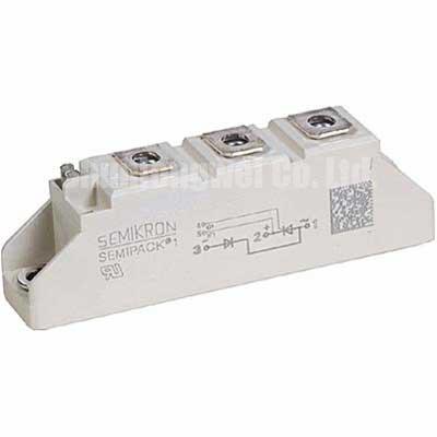
Design Consideration: Thyristor turn-off depends on current extinction and recovery before forward blocking voltage returns. Diode reverse-recovery peak current and recovery time describe a different commutation behavior and should be evaluated for the actual diode in the circuit. They are not interchangeable with thyristor turn-off characteristics. The manufacturer’s SEMIPACK thyristor and diode module information provides the relevant product-family context.
When an associated rectifier stage includes a device such as SKKD 81/12, evaluate its recovery behavior within that stage’s current path. As a Design Consideration, inspect snubber connections and any MOV absorption network together: clamping behavior, repetitive energy duty, and wiring inductance affect the voltage reaching the module. Component selection and acceptance limits should follow measured system transients.
The Evolution of Negative Off-Bias Gate Drive Circuits discusses a separate gate-drive topic; it does not establish an SKKT92B12E negative-bias setting or an operating-lifetime guarantee. Thyristor firing and recovery checks should remain tied to this device’s gate limits and commutation conditions.
Assembly Integrity & Layout Architecture: Assessing Surge Current Limits for SKKT92B12E
Compare the fault-current waveform with the Official Specification of 1500 A surge on-state current, ITSM, for 10 ms, preserving the manufacturer’s waveform, initial-temperature, and voltage-reapplication conditions in the assessment. A surge rating does not establish a repetitive operating current. For fuse coordination, compare the fuse’s total clearing I²t with the module’s applicable withstand data under matching conditions.
Engineering Recommendation: Inspect heatsink flatness, mounting contact, terminal seating, and thermal-interface coverage before recommissioning. Obtain mounting torque, terminal torque, insulation-test conditions, and thermal-interface instructions from the applicable assembly documentation; these are separate acceptance items. The Semikron-Danfoss official hub provides access to manufacturer resources.
For compatibility assessment in a grid-tied static var compensator or thyristor-switched capacitor assembly, designers should verify branch topology, capacitor-switching transients, cooling, and firing synchronization. As a Design Consideration, parallel paths require measured static and dynamic current sharing; do not assume a favorable temperature coefficient establishes balanced operation. After a surge event, assess thermal recovery and voltage reapplication against the equipment’s protection sequence before returning the branch to service.