


Content last revised on September 18, 2026
Benchtop Waveform Tuning: Mitigating Stress via Power Factor Degradation and Harmonics on 2DI100D-050
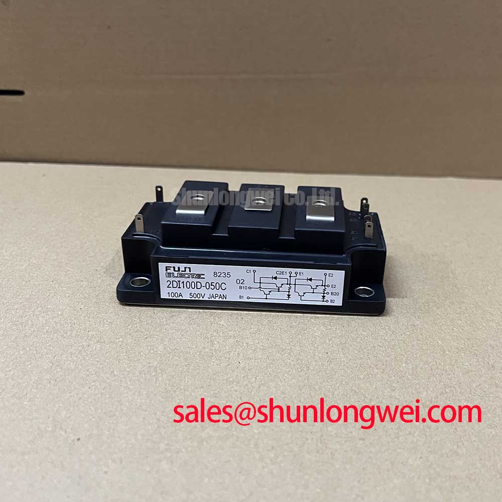
With the cabinet isolated and discharged, confirm the nameplate boundary of the Fuji Electric 2DI100D-050 against the original schematic before disconnecting its power terminals. This dual diode module has a specified 500 V voltage rating and 100 A rated current under the applicable conditions. Confirm all operating limits against the original equipment documentation and protection scheme.
In a grid tied static var compensator or thyristor switched capacitor installation, the 2DI100D-050 should be treated as a power rectification or freewheeling element within the existing topology, not as a device that sets firing angle, reactive power, or power factor by itself. Those functions are determined by the controller, thyristor valve arrangement, capacitor bank, reactor network, and grid conditions.
During a controlled bench evaluation, maintenance personnel should compare AC line voltage, load current, and diode branch voltage waveforms with the known system sequence. Changes in firing angle from the upstream controlled bridge can change current conduction intervals, harmonic content, and thermal loading. A distorted current waveform does not establish a diode fault on its own. Confirm the source waveform, commutation path, snubber condition, and branch connections before assigning a cause to the module.
For a diode module installation, system engineers should use the documented junction-to-case thermal resistance for the relevant diode path when making a thermal estimate. This is an Engineering Calculation input, not a complete heatsink temperature prediction.
Maintenance Note: Inspect heatsink airflow, accumulated dust, ageing thermal interface material, and terminal tightness during planned service because elevated contact temperature can change current sharing and accelerate unplanned downtime.
2DI100D-050 Thermal Electrical Optimization: Fuse Total Clearing I2t versus Device Melt Practical Tuning
Fuse coordination should begin with the equipment manufacturer’s approved protection data rather than an assumed diode damage threshold. The supplied official parameters define voltage, current, and junction-to-case thermal resistance, but they do not provide a published fuse total clearing I2t coordination limit for this page. It would therefore be inappropriate to assign a numerical fuse I2t value to the 2DI100D-050.
As a Design Consideration, compare the semiconductor fuse pre-arcing and total clearing characteristics against the prospective fault current, circuit inductance, conductor arrangement, and the protection sequence already used in the SVC or capacitor switching panel. The relevant question is whether the protection clears the dead short before energy delivered through the branch exceeds the limits established by the original system design and applicable module documentation.
Check all power terminal interfaces for flat contact faces, correct hardware, and the tightening procedure specified by the equipment builder. Mounting force and terminal torque are mechanical installation requirements, not published ratings in the supplied 2DI100D-050 parameter set. When a direct service comparison is required, the related 2DI100D-050C should be evaluated against the complete original drawing, terminal arrangement, thermal interface, and protection circuit.
Benchtop Waveform Tuning: Mitigating Stress via Non-Repetitive Surge On-State Current on 2DI100D-050
The supplied official data does not state an ITSM sinusoidal half-cycle surge rating. Do not infer a surge current value from the 100 A rated current or from other device parameters. These parameters describe different electrical conditions and cannot replace a manufacturer-stated non-repetitive surge specification.
For troubleshooting after an overload event, isolate the assembly and inspect the fuse status, branch busbars, snubber components, heatsink contact surface, and diode voltage waveform during a controlled restart. Unexpected heating or asymmetric current paths may indicate a wider circuit issue, including unequal branch impedance or changed switching timing. Verification should use the original equipment limits and an oscilloscope measurement referenced to a known good signal path.
Thermal cycling is influenced by load variation, cooling performance, and mechanical contact quality. The thermal expansion coefficient relationship in semiconductor assemblies is relevant as a Design Consideration when reviewing repeated heating and cooling of a clamped power module and its heatsink. It does not provide a field life prediction for this specific part.
Transient Dynamics & Electrical Design: AC Input Transient Overvoltage Clamping on 2DI100D-050
Verify that measured peak device stress remains within the specified device voltage rating under the applicable switching and line-transient conditions. MOV and RC snubber selection belongs to the complete system design because the required clamping behaviour depends on the AC source, cable routing, transformer characteristics, capacitor bank arrangement, existing suppression network, and expected transient environment.
As an Engineering Recommendation, minimize parasitic loop inductance around the protected power path to suppress transient overshoot, then verify peak margins against the branch voltage and the diode’s specified voltage rating during instrumented switching tests. A snubber that changes the observed waveform may also alter dissipation elsewhere in the assembly, so its effect should be evaluated at the component and system level.
For enclosures exposed to dust, humidity, or condensation risk, assess cabinet sealing, ventilation, and drainage against the actual installation environment. The IP code framework for dust and water ingress helps define enclosure protection categories, but it is not a performance certification for the diode module itself. For broader power conversion context, review The 1200 V CoolSiC™ MOSFET Advantage in Three-Phase Power Conversion while keeping the 2DI100D-050 evaluation tied to its own official ratings and original circuit requirements.