
Content last revised on September 19, 2026
2DI30A-140 Operational Boundaries: Evaluating Thermal Interface Material Spreading Across Limits
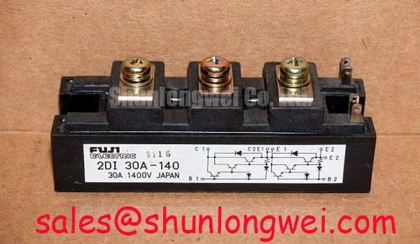
Before installation, verify the nameplate against the replacement record and confirm that the device is a Fuji Electric 2DI30A-140 rated at 1400 V and 30 A in a Power Diode Module package. These are Official Datasheet Specifications. Check the module body, terminals, and mounting face for contamination, damage, or deformation before it is placed on the heatsink.
The thermal interface deserves the same attention as the electrical connections. Apply thermal compound uniformly across the contact face according to the equipment manufacturer’s assembly instructions, then tighten the specified hardware in an even sequence. Uneven clamping can reduce contact consistency, while excessive force can distort the package or compromise terminal alignment. The original Fuji Electric documentation should be used to confirm the applicable mounting hardware, torque, terminal arrangement, isolation requirements, and thermal resistance values for this exact module.
Field Alert: Disconnect, lock out, and verify the DC and AC energy paths are discharged before loosening module terminals or removing a diode assembly.
Design Consideration: A high voltage three phase motor solid state soft starter should be evaluated as a complete thermal system. Heatsink condition, airflow, enclosure temperature, phase loading, and the firing profile determine junction stress in service. The 30 A current rating is an official device boundary, not a substitute for checking the actual conduction waveform and cooling conditions of the installed starter.
Assembly Integrity & Layout Architecture: Implementing I2t Sub Cycle Melting Rating for 2DI30A-140
For a diode module assembly, fault protection begins with the actual circuit topology and the prospective fault current at the installation point. Semiconductor fuse coordination should be reviewed against the diode module’s official surge and I2t data from the original Fuji Electric datasheet. No fuse clearing I2t value, surge current limit, or short circuit withstand value should be assigned to the 2DI30A-140 without that source documentation.
Engineering Recommendation: Compare the fuse manufacturer’s pre arcing and total clearing characteristics with the system fault study, conductor impedance, transformer capability, and the protected diode path. The objective is to limit fault energy before it exceeds the semiconductor and mechanical limits of the assembly. This verification is particularly important where a soft starter includes line connected power sections with substantial available fault energy.
Keep the high current buswork compact and mechanically secure, with matched current-path routing where the existing assembly permits it. This is a Design Consideration for reducing unequal current paths and transient stress during abnormal events. Inspect crimping, lug seating, insulation spacing, and terminal torque against the equipment documentation. For related rectifier capacity evaluation, engineers can compare the electrical and mechanical requirements with the 2DI100Z-140; compatibility must be established from the complete system specification rather than the part number alone.
Field Diagnostics & Commissioning: Gate Trigger Current Dynamics in 2DI30A-140 Topologies
The 2DI30A-140 is specified as a Power Diode Module, so it has no gate trigger current, gate firing pulse, Miller plateau, negative gate bias, or active clamp function. Those controls belong to separate thyristor, IGBT, or gate driver elements that may exist elsewhere in a soft starter circuit. Treating diode terminals as gate controlled connections can lead to an incorrect commissioning procedure.
During field diagnosis, isolate the module from energized circuitry as required by the service procedure and compare each diode path with the expected module schematic using appropriate test equipment. A measurement that differs from the known circuit path may indicate a connection issue, a parallel component influence, or device damage; confirm the result after accounting for connected snubbers, fuses, control wiring, and other semiconductor paths. Avoid deriving a pass or fail decision from one generic diode meter reading.
When the surrounding topology includes controlled rectification or soft start firing circuits, examine trigger waveforms at the actual controlled devices and use the original equipment schematic to identify their gate return paths. Fuji Electric’s power semiconductor portfolio provides useful product family context, but it does not replace the specific documentation for the installed diode module. For a higher current sibling assessment, the 2DI75A-140 should be reviewed against electrical ratings, terminal layout, cooling, and system protection requirements.
Transient Dynamics & Electrical Design: Thermal Avalanche Margins during High Peak on 2DI30A-140
Do not assume avalanche capability, a sinusoidal 10 ms surge rating, or reverse recovery performance for the 2DI30A-140 unless the original Fuji Electric datasheet explicitly publishes those values and their test conditions. The official information available here establishes 1400 V, 30 A, and the Power Diode Module package. These values should be verified against measured line conditions and the system’s maximum repetitive and transient voltage exposure.
Design Consideration: Reduce parasitic loop inductance in the commutation path to suppress turn off overshoot, then verify peak voltage margins against the DC link and device rating during controlled switching tests. In a three phase motor soft starter, phase imbalance, commutation behavior, line disturbances, and protective circuit operation can all affect diode stress. Test results should be assessed by the system engineer under representative load and fault conditions.
Where regenerative braking or a braking chopper exists in adjacent equipment, its energy handling path should be evaluated independently from this diode module. Likewise, bootstrap capacitor operation and driver diode recovery belong to the gate driver subsystem, not to the 2DI30A-140. For broader context on switching loss and industrial drive architecture, see Unlocking Efficiency in Industrial Drives. Fuji Electric also describes its PIM 7 Pack product family, which should be considered separately from the diode module when evaluating system level power stages.