
Content last revised on October 29, 2026
Assembly Integrity & Layout Architecture for 2MI50F-050
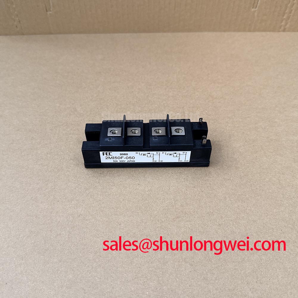
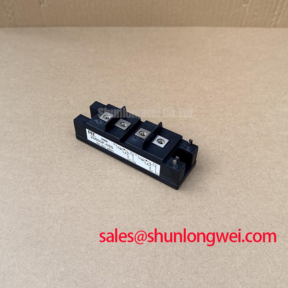
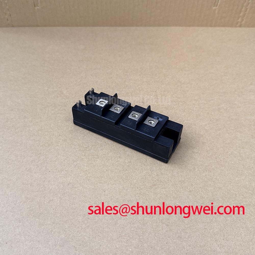
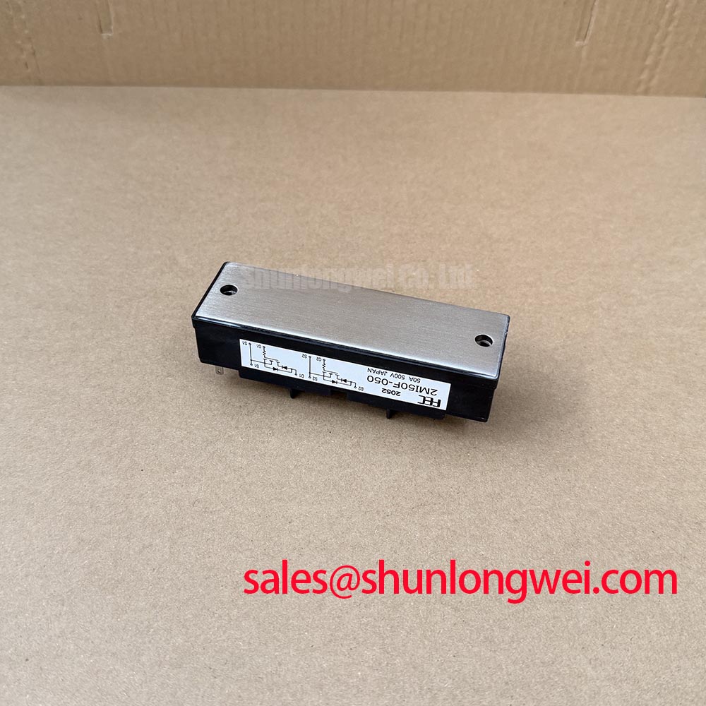
Mechanical installation should begin with a clean heatsink surface and a controlled inspection of the module base, mounting holes, terminals, and surrounding insulation. The published product information confirms the electrical rating and module package, but it does not establish a manufacturer-approved thermal interface thickness, mounting torque, baseplate flatness tolerance, or internal construction detail. These values should therefore be taken from the applicable Fuji Electric datasheet or the original drive service documentation.
As a Design Consideration, the thermal interface should be applied evenly without trapped air pockets, excessive material, or contamination on the heatsink. Engineers evaluating a replacement should check the contact pattern after removal, inspect for hardened or displaced thermal compound, and confirm that the heatsink remains flat enough for uniform pressure. Mounting hardware should be tightened progressively in the sequence specified by the equipment manufacturer rather than relying on a generic torque value.
Keep the high-current commutation path physically compact and avoid routing sensitive control wiring alongside the power loop. The system layout should also preserve the original creepage, clearance, and service access arrangement. ⚠️ Maintenance Note: Isolate the drive from all energy sources before disconnecting the module, and monitor heatsink contact temperature during commissioning after cleaning the air path.
2MI50F-050 Circuit Protection & Reliability
The 2MI50F-050 rating of 500.0 V and 50.0 A (with standard 2500V AC isolation) defines important product identification boundaries, but it does not by itself specify surge current capability, short-circuit withstand time, isolation test voltage, common-mode transient immunity, or semiconductor fuse coordination. Those characteristics must be verified from the exact Fuji Electric documentation associated with the module and from the drive manufacturer’s protection schedule.
For a replacement assessment, inspect the gate drive board, gate resistor network, feedback circuits, and DC-link discharge path before applying switching power. A low resistance reading across the power terminals may indicate damage, but diagnosis should compare all equivalent legs and use the original circuit diagram rather than treating one measurement as conclusive. Protection design should coordinate the semiconductor fuse clearing characteristic with the module’s documented transient and short-circuit limits. The required I²t relationship is system dependent and must be confirmed during controlled fault testing.
Reinforced insulation and common-mode behavior should also be verified at system level. Do not assign a specific isolation or CMTI value to this module without a supporting Fuji Electric source. Fuji Electric’s Power Semiconductor and IPM Modules information can help engineers locate the relevant product family documentation.
2MI50F-050 Operational Boundaries: Output Filter and dv/dt Reactor Evaluation
When this module is evaluated in a heavy-duty variable frequency AC motor drive, the output network must be reviewed together with motor cable length, cable construction, motor insulation, switching frequency, and grounding practice. Long motor leads can create impedance mismatch and reflected-wave stress at the motor terminals. The often-discussed terminal overshoot relationship is not a guaranteed value for this model; actual peak voltage should be measured with a suitable differential probe at both the inverter output and motor terminals.
A sinusoidal filter and a dv/dt reactor perform different functions and should not be selected interchangeably. The filter manufacturer’s impedance, current rating, thermal behavior, resonance limits, and installation instructions must be matched to the drive. Designers should verify that the selected network does not interfere with current regulation, create excessive leakage current, or shift the protection response outside the drive’s intended operating range.
The upstream rectifier and DC-link arrangement also affect the switching stage. In a complete power conversion chain, engineers may evaluate the related CM50DY-28H as a neutral reference for an associated power stage, while confirming voltage, current, topology, and mechanical compatibility independently.
Benchtop Waveform Tuning for Turn-Off Stress on 2MI50F-050
During bench testing, measure the collector-emitter voltage, gate-emitter waveform, and current transition with probes whose bandwidth, grounding, and common-mode rating suit the test voltage. Turn-off overshoot is influenced by DC-link voltage, commutation current, stray inductance, gate resistance, switching speed, and measurement-loop inductance. In engineering terms, the peak voltage rises as the inductive voltage associated with stray inductance and current change is added to the applied DC-link voltage, so the acceptable clamp level must be established from the module’s documented voltage boundary and the complete drive design.
Use a compact, symmetrical busbar arrangement where practical, minimize the commutation loop, and place snubber components according to the measured switching node rather than by physical convenience. Snubber capacitance, damping resistance, and gate-drive tuning are system-determined values. The engineer should verify peak margins over the intended load-current and temperature range with an oscilloscope and compare the result with the known-good drive waveform.
For broader switching-layout context, the technical discussion in Unlocking Efficiency in Industrial Drives provides a useful comparison point, while the Fuji Electric Power Semiconductors Portal should be consulted for product-specific documentation. Compatibility with an alternative such as 3MBI50SX-120-02 requires independent verification of electrical ratings, pin arrangement, mechanical dimensions, gate-drive requirements, and protection settings.