Content last revised on September 24, 2026
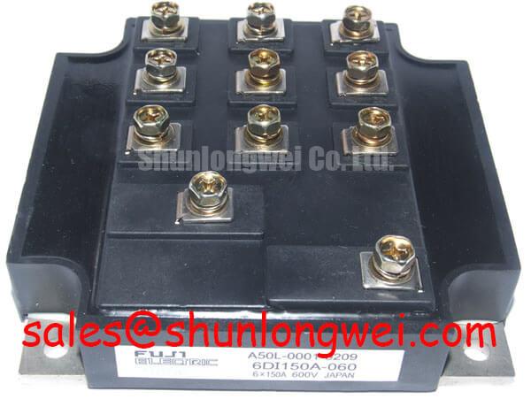
Fuji Electric 6DI150A-060 Replacement and Application Verification
Before installing a replacement, isolate the drive, inspect the module body and terminals, and verify the nameplate boundary of 600 V and 150 A against the original circuit documentation.
| Manufacturer | Fuji Electric |
| Model | 6DI150A-060 |
| Voltage Rating | 600.0 V, Official Specification |
| Current Rating | 150.0 A, Official Specification |
| Package | Power Transistor Module, Official Specification |
The Fuji Electric 6DI150A-060 is a 600 V, 150 A power transistor module evaluated by maintenance teams for industrial inverter and heavy-duty variable-frequency AC motor drive repairs. The values listed above are the available official product parameters. Gate-drive voltage, switching energy, short-circuit withstand time, thermal resistance, terminal arrangement, and braking configuration should be confirmed from the original Fuji Electric documentation before circuit replacement.
Preventing Spurious Faults: High-Frequency Common-Mode Bearing Current Guidelines for 6DI150A-060
Long motor leads can interact with cable impedance, motor capacitance, and the inverter switching edge. Reflected-wave behavior may increase terminal stress and common-mode current, particularly when the drive output wiring differs from the original installation. This is a system-level design consideration, not a guaranteed operating condition of the 6DI150A-060. Designers should evaluate the motor cable route, shield termination, grounding arrangement, and measured phase-to-ground voltage during switching tests.
When a heavy-duty AC drive develops intermittent overcurrent, earth-leakage, or bearing-current symptoms, compare the affected output phase with a known-good phase using an appropriately rated oscilloscope probe. Check the output filter, common-mode choke, and motor cable termination as one network rather than assigning the fault to the module alone. A dv/dt filter or output choke may reduce edge stress, but its electrical characteristics must be matched to the drive carrier frequency, motor insulation system, cable length, and control response.
The Fuji Electric Power Semiconductor and IPM Modules reference provides useful manufacturer-level context for power semiconductor integration. The system engineer should verify creepage, clearance, and probe safety against the actual DC-link voltage and enclosure geometry.
Assembly Integrity and Layout Architecture: Implementing Hard-Switching Transient Mitigation for 6DI150A-060
During replacement, preserve the original power-loop geometry wherever possible. Minimize the commutation loop area to limit parasitic inductive overshoot, then verify the peak collector-emitter voltage during turn-off with a suitable differential probe. The 6DI150A-060 official data supplied here does not specify a short-circuit response time or SCSOA limit, so protection timing must not be inferred from the model number.
A gate driver should be evaluated for both sourcing and sinking capability, propagation delay, desaturation or overcurrent response, and controlled fault turn-off. External gate resistance is a typical starting-point tuning element: increase damping when ringing is visible, but validate switching loss and junction-temperature behavior after every adjustment. The correct value is system-determined by gate charge, driver impedance, layout inductance, switching frequency, and required thermal margin.
Where the original assembly uses separate power and signal returns, keep those paths functionally separated and confirm the manufacturer’s terminal definition before wiring. A two-stage soft turn-off strategy may reduce fault-induced overshoot, but its timing and gate-voltage profile require bench validation against the actual driver and protection circuit.
Transient Dynamics and Electrical Design: Sizing Braking Resistors and Chopper Transistors on 6DI150A-060
In a variable-frequency AC motor drive, deceleration energy can raise the DC-link voltage when the motor regenerates. The braking transistor and resistor network must be assessed together with the DC-link capacitor, braking duty cycle, acceleration profile, and protective trip level. The 600 V rating of the 6DI150A-060 is an official device parameter; it is not a substitute for calculating the complete transient voltage margin of the drive.
For replacement evaluation, inspect the braking resistor for discoloration, cracked ceramic, loose connections, and evidence of repeated thermal cycling. Confirm that the control board commands the chopper only under the intended DC-link conditions, then observe the bus voltage during controlled deceleration. Resistor pulse energy, average power, cooling airflow, and enclosure temperature should be calculated from the actual machine duty rather than selected from the module current rating alone.
The 6MBI15L-060 may be reviewed as a neutral reference for a related power-conversion stage when examining the broader topology. It should not be treated as an automatic substitute for the 6DI150A-060; voltage, current, terminal configuration, gate-drive requirements, and mechanical fit must be independently verified.
6DI150A-060 Circuit Protection and Reliability: PCB Symmetry Considerations for Dual IGBT Layouts
In a dual-switch power layout, unequal emitter return paths can introduce shared inductance and unwanted feedback into the gate-drive loop. The practical design consideration is to keep high-current commutation paths short and symmetrical while routing the gate-drive return separately from the main power return wherever the verified terminal structure permits it. Do not assume an auxiliary or Kelvin emitter connection unless it is explicitly shown in the original terminal diagram.
Inspect solder joints, busbar interfaces, mounting pressure, and signs of localized heating before applying power. After installation, measure phase balance, gate waveform symmetry, and collector-emitter overshoot under controlled load. If oscillation or unequal switching appears, compare the physical loop geometry and driver return path before changing gate resistance.
⚠️ Maintenance Note: Clean the heatsink and verify thermal-interface material condition during scheduled service, then monitor contact temperature and airflow after reassembly.
For structured inspection methods covering testing, failure analysis, and reliability practice, consult the Field Engineer’s Handbook. The Fuji Electric PIM 7-Pack reference can also help engineers distinguish general module topology information from the specific verified parameters of the 6DI150A-060.