
Content last revised on October 4, 2026
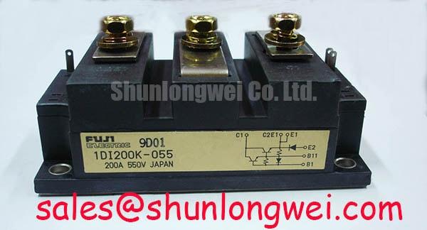
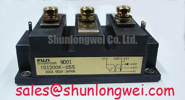
1DI200K-055 Product Details
| Model | 1DI200K-055 |
|---|---|
| Manufacturer | Fuji Electric |
| Product category | Power transistor / Darlington module |
| Package | Power Transistor Module |
| Rated current | 200 A (Official Specification) |
| Voltage rating | Not specified in the supplied product parameters |
Heatsink Contact and Mounting Checks for 1DI200K-055
Check the heatsink contact pattern and mounting screws when a repaired drive develops temperature-related trips under load. A loose mounting point, uneven interface compound or debris beneath the 1DI200K-055 can impair heat transfer without producing an obvious cold-state electrical fault. Isolate the equipment, discharge its stored energy and inspect the mating surfaces for raised edges, contamination and uneven compound transfer.
For reassembly, apply thermal interface material as a thin, continuous layer rather than using it to fill a visibly distorted mounting surface. Avoid trapped air and tighten mounting screws progressively so the module seats evenly. These are Design Considerations, not Fuji Electric mounting specifications for this model; use the equipment service instructions to establish the compound, fastening sequence and torque. If the baseplate or heatsink appears bowed, investigate the mechanical fit rather than assuming additional compound will correct it. Field Alert: Do not tighten a module against a contaminated heatsink surface.
Record heatsink temperature and trip timing during a controlled load test, then compare them with the equipment’s previous service readings if available. A rising temperature alone does not identify the failed part: cooling airflow, load current and interface contact all warrant checks. The Advanced Thermal Management Revolution provides broader context for assessing the thermal path without assigning an unverified internal construction to this module.
Altitude and Operating Margin Checks for 1DI200K-055
Measure DC-bus voltage and cabinet temperature at the operating site before attributing an intermittent trip to altitude. The supplied parameters establish a 200 A current rating, but give no numeric voltage rating, altitude limit, switching-frequency range or radiation-related failure rate for 1DI200K-055. A calculation of single-event burnout probability or failures in time would therefore be unsupported.
As a Design Consideration, installations at elevated altitude may require an equipment-level review of cooling and electrical clearances. Record the site conditions, fan operation, load profile and switching settings, then assess them against the drive maker’s requirements. Do not infer an allowable DC-bus margin from the module’s current rating. If service records show trips only during high ambient temperatures or sustained load, compare airflow and temperature trends before changing protection settings.
A heavy-duty variable-frequency AC motor drive is a possible application to evaluate, not an established installation for this part. Confirm the original circuit topology, transistor voltage rating and thermal limits from the equipment documentation before considering an in-place replacement. QM200HA-HK may be included in a parts comparison, but its terminal arrangement, electrical ratings, drive requirements and mounting fit must be checked independently; the shared current figure does not establish interchangeability.
Motor-Lead Transients and Output Filtering
Probe the motor-terminal waveform with appropriately rated equipment when a drive trips after a cable change or an output-filter repair. Compare the observed peaks with the drive’s DC-bus waveform and the equipment maker’s limits. Long leads can produce reflected-wave effects, but no fixed spike multiple, permissible cable length or filter value can be assigned to 1DI200K-055 from the supplied product parameters.
When evaluating a sinusoidal output filter or a dv/dt reactor, start with the drive and motor requirements: cable length, carrier setting, motor insulation and permitted output loading. A filter selected for one installation may alter current, heating or protection behavior in another. Keep power connections mechanically secure, inspect cable routing and verify clearance against the assembly drawings. The system designer should select and validate the filter through switching tests under the actual load rather than treating it as a property of the transistor module.
If an output fault persists, check the protection path as well as the power stage. A semiconductor fuse cannot be judged by current rating alone; its clearing characteristics and energy coordination belong to the complete circuit design. Cold-state resistance checks across the module terminals can help screen for an obvious short, but readings should be compared with a known-good assembly and the verified circuit diagram.
Drive-Terminal Diagnostics Before Commissioning
Measure the drive signal at the transistor control terminals when commissioning reveals unexpected conduction or a protection trip. 1DI200K-055 is identified here as a power transistor / Darlington module, so an IGBT gate-bias or active Miller-clamp prescription must not be applied to it without confirming the actual device circuit. Trace the installed drive board and terminal functions first; then compare its waveforms with the equipment service documentation.
Inspect the drive supply, isolation path and turn-off behavior under controlled conditions. If the equipment uses a bootstrap supply elsewhere in its switching circuit, assess capacitor recharge and diode recovery in that circuit rather than assigning those features to this module. Likewise, inspect protection timing and the command sequence when investigating suspected simultaneous conduction; a cold multimeter reading cannot establish dynamic switching behavior.
Fuji Electric’s V-Series IGBT Application Manual discusses IGBT drive and switching considerations, while its PIM product information describes a different module category. Neither establishes the terminal functions or limits of this Darlington module. Commission against the original equipment schematic and confirmed device specifications, observing the actual control waveform and protection response before returning the drive to load.