
Content last revised on September 10, 2026
1MBI300NN-120 Installation and Service Context
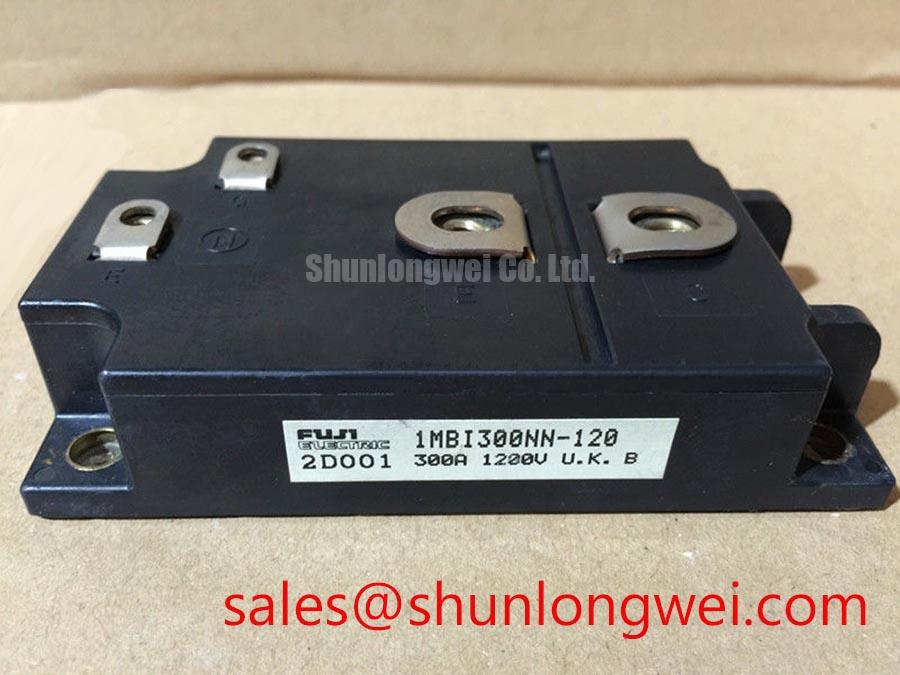
Before installation, verify the equipment nameplate and circuit documentation against the 1MBI300NN-120 marking, then inspect the module housing, terminals, busbar contact faces, and heatsink interface for contamination, corrosion, loosened hardware, or signs of previous overheating. This Fuji Electric power semiconductor is specified as a 1200.0 V, 300.0 A IGBT Module according to the available official product data. Those ratings establish the module identity, but the original equipment documentation remains essential for confirming topology, gate-drive arrangement, protection thresholds, terminal assignment, and thermal assembly requirements.
For maintenance teams working on industrial inverter welders or medium-frequency induction-heating power supplies, the practical task is to restore the original switching assembly without assuming that every module in a similar physical format has matching electrical behaviour. Confirm the DC-link operating range, the intended current path, the driver-board interface, and the associated protection circuit before energising the machine. The 1200.0 V and 300.0 A values are Official Datasheet Specifications; no additional switching-loss, gate-charge, thermal-resistance, isolation, or surge-current values should be inferred without the applicable Fuji Electric documentation for the installed equipment.
Benchtop Waveform Tuning: Mitigating Stress via Thermal Cycling Margins of Internal Braking on 1MBI300NN-120
A bench inspection of a drive or power-conversion cabinet should first establish whether the 1MBI300NN-120 is installed in a switching leg, a chopper position, or another circuit function defined by the machine manufacturer. The available product information identifies the module by voltage, current, manufacturer, and package category, but it does not establish that this particular model contains an internal braking device. Treat braking-circuit configuration as an equipment-level question. The service engineer should trace the DC-link, braking resistor, switching device, and control wiring against the original schematic before connecting an oscilloscope or applying power.
In systems that dissipate deceleration energy through a braking branch, the ballast resistor, wiring, protective devices, and control logic must be evaluated as one assembly. Energy returned by a motor can raise the DC-link voltage when the supply cannot absorb it. A braking circuit is intended to direct that energy into a resistor when the system control determines that action is required. This is a Design Consideration, not an official functional claim for the 1MBI300NN-120. Engineers should verify resistor duty capability, cooling airflow, thermal clearance from nearby wiring, and the original controller’s braking threshold through the equipment documentation.
During bench tuning, use a differential measurement method appropriate to the expected common-mode conditions and compare switching waveforms with a known-good machine or validated commissioning record where available. Ringing, irregular turn-off transitions, or unexpected DC-link excursions may reflect more than one condition, including busbar layout changes, degraded DC-link capacitors, altered gate-drive impedance, probe grounding error, or a problem in the braking path. Isolate the evidence before changing component values. Avoid treating a waveform shape alone as proof of a failed module.
Clear physical separation between resistor wiring, sensitive control cables, and high-current commutation conductors helps maintenance teams keep fault finding repeatable. Keep current-carrying paths short and mechanically secure, while preserving the original creepage and clearance provisions of the equipment. If an installation review requires a comparative reference, the 6MBI300U-120 can be examined as a separately listed Fuji Electric module, but its topology, electrical ratings, terminal arrangement, driver requirements, and mechanical fit must be checked independently rather than presumed equivalent.
⚠️ Maintenance Note: Periodically check terminal contact temperature rise during controlled operation and confirm that heatsink fins, fan inlets, and cabinet airflow paths remain free of dust accumulation.
1MBI300NN-120 Thermal-Electrical Optimization: Turn-Off di/dt Induced Vpeak Clamping and Practical Tuning
Turn-off evaluation begins with the real commutation loop, not with the module in isolation. When current is interrupted, the observed voltage can rise above the DC-link level because unavoidable loop inductance reacts to the rate of current change. In engineering terms, the peak is influenced by the DC-link voltage plus the inductive contribution created by loop inductance and turn-off di/dt. This relationship is an Engineering Calculation principle, but a safe limit cannot be calculated from the available 1200.0 V, 300.0 A identification data alone. Actual busbar inductance, switching speed, operating temperature, probe arrangement, and the device’s applicable transient ratings must be established from the complete system and manufacturer documentation.
For a practical maintenance review, inspect laminated or planar busbars, capacitor-to-module connections, DC-link fasteners, and the return path used by the gate driver. The objective is to minimise parasitic loop inductance where it contributes to turn-off overshoot, then verify peak voltage margin against the real DC-link condition during controlled switching tests. Do not introduce a snubber capacitor, resistor, or gate resistor value as a universal correction. Snubber selection is system-determined because it changes resonant behaviour, dissipation, switching loss, and electromagnetic emissions.
Gate-driver wiring deserves the same attention as the power loop. A loose auxiliary connection, an extended gate-return path, or a damaged driver isolation barrier can affect switching behaviour and protection response. Where the original circuit has a separate low-inductance reference or auxiliary return connection, retain its documented routing and do not combine it casually with a high-current power return. The available structured specifications do not confirm a Kelvin-emitter terminal arrangement for this model, so terminal roles must be verified from the original module drawing and the equipment schematic.
Freewheel-diode recovery behaviour can also shape commutation stress and conducted or radiated noise. Reverse-recovery softness is sometimes described using a softness factor, but no official value is provided here for the 1MBI300NN-120. Therefore, it should not be assigned a numerical value or used to predict emissions performance. If conducted noise, switching ringing, or driver disturbance is being investigated, compare voltage and current waveforms across the original signal path and inspect capacitor ESR, connector integrity, shield terminations, and mechanical busbar alignment.
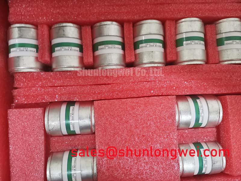
Fuse coordination is another assembly-level verification. A high-speed semiconductor fuse must be evaluated for its clearing behaviour, let-through energy, prospective fault current, and coordination with the applicable module and system protection limits. This is an Engineering Recommendation for fault containment, not an assertion that any specific fuse is suitable for the module. Review the original fuse documentation and protection study before restoring a machine to service.
Fuji Electric publishes technical information on brake chopper IGBT modules. That material can provide useful category context when assessing braking hardware, while the installed circuit and the documentation specific to the 1MBI300NN-120 remain the controlling references for service work.
1MBI300NN-120 Operational Boundaries: Evaluating Failures in Time Rates in High Limits
Do not assign a failures-in-time rate, a single-event burnout probability, or an operating-life prediction to the 1MBI300NN-120 from its stated voltage and current ratings. No qualified FIT data, neutron-flux test result, altitude derating curve, or single-event qualification result is included in the provided official product information. Such values require a defined test method, environmental model, voltage condition, temperature condition, and an authoritative source. Presenting an unverified number would not support a reliable repair or procurement decision.
High-altitude installations should instead be approached as a Design Consideration for the complete power assembly. Reduced air density can alter cooling performance and external insulation behaviour, while local site conditions may also change contamination, humidity, and condensation exposure. The system integrator should verify enclosure sealing, airflow, heat-exchanger performance, spacing, and the original equipment manufacturer’s altitude guidance. These matters concern the assembled cabinet and its installation environment; they cannot be certified by the module’s 1200.0 V, 300.0 A identification data.
For preventive maintenance, record the operating load pattern, heatsink condition, fan performance, cabinet temperature trend, and any repeated fault timestamps before replacing a power module. A thermal problem may arise from restricted airflow, degraded interface material, unequal mounting pressure, loose terminals, or a control condition that causes abnormal switching duty. Inspect the thermal interface during planned shutdowns and use the equipment manufacturer’s assembly process for cleaning, application material, tightening order, and torque. The available official data does not specify mounting torque, thermal impedance, or maximum junction-temperature limits, so those parameters must not be substituted with generic values.
Humidity control is equally relevant in cabinets subject to day-to-night temperature swings. Condensation on driver boards, terminals, or exposed busbar surfaces can lead to leakage paths, corrosion, intermittent gate signals, or inaccurate sensor readings. Allow a cabinet to reach a stable, dry condition before insulation-related testing or re-energisation. If the fault history indicates a recurring environmental influence, inspect heater operation, door seals, cable entries, drain paths, and the condition of conformal protection already present in the original design.
When a machine shows repeated switching-related trips without an obvious module short circuit, preserve waveform captures and control-event records before changing the power stage. The technical discussion in Unlocking Efficiency in Industrial Drives can assist with broader industrial-drive troubleshooting concepts. It should be used as contextual engineering information rather than as a specification source for the Fuji Electric 1MBI300NN-120.
Preventing Spurious Faults: Negative Gate Bias vs Active Miller Clamp Guidelines for 1MBI300NN-120
A false turn-on event is a system-level risk that should be investigated at the gate-driver interface, power-loop geometry, and measurement setup together. During rapid voltage transitions, capacitive coupling within a switching assembly can disturb the gate-emitter voltage of a non-commanded switch. Depending on the driver design, this disturbance may contribute to cross-conduction, nuisance protection activity, distorted waveforms, or unexplained heating. The correct remedy depends on the original drive architecture and must be validated under representative operating conditions.
Negative gate bias and active Miller clamping are established gate-drive techniques, but neither should be applied to the 1MBI300NN-120 as a generic retrofit instruction. The available official information does not specify permitted gate voltage, recommended off-state bias, clamp threshold, gate resistance, or driver topology. Designers should consult the applicable Fuji Electric datasheet and the original driver-board documentation before changing any gate-drive supply or adding an active clamp. A change that improves immunity in one layout can alter switching loss, overshoot, timing, or protection behaviour elsewhere in the system.
Start diagnosis by checking that the driver supply is stable, the control-reference path is intact, connector pins are secure, and the intended gate-return routing has not been modified during service. Then observe the commanded and non-commanded gate signals with probes suitable for the isolation and common-mode environment. Compare these observations with collector-emitter voltage and load current, using the known-good path where possible. A gate signal anomaly may indicate coupling, driver degradation, reference movement, protection interaction, or measurement artefact; it should not be attributed to a single cause without corroborating evidence.
For industrial inverter welders and medium-frequency induction-heating equipment, retain the original separation between high-current power conductors and low-level driver or feedback wiring. Check cable shields and chassis bonding according to the machine documentation, inspect optocouplers or digital isolators for supply and signal integrity, and verify that any fault interlock remains functional after service. Common-mode transient immunity is a property of the specific isolation device, circuit layout, and operating condition, not a published property of this IGBT Module based on the limited available specifications.
Before returning equipment to production, perform controlled functional checks at conditions approved by the responsible system engineer. Confirm correct start-up sequencing, stable driver behaviour, protection response, heatsink airflow, and the absence of abnormal waveform movement as load changes. This disciplined process keeps the repair focused on the documented capabilities of the Fuji Electric 1MBI300NN-120 and the verified operating boundaries of the complete power system.