Content last revised on September 19, 2026
Field Diagnostics & Commissioning: High-Frequency Switching Loss Dissipation in 2DI150D-100 Topologies
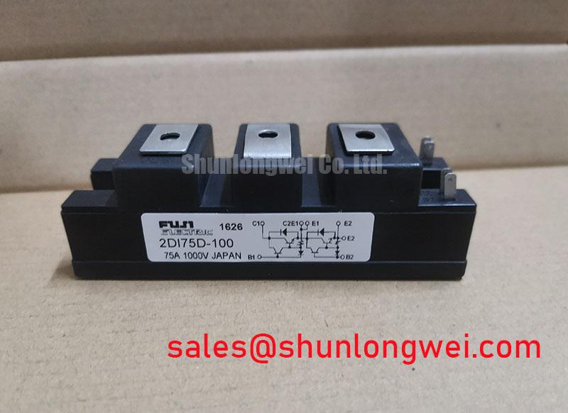
Verify the nameplate against the replacement record, inspect the power terminals and case for mechanical damage, and confirm that the circuit application requires a 1000.0 V, 150.0 A diode module before energizing the assembly. The Fuji Electric 2DI150D-100 is specified as a power diode module for high-power rectifier and power-conversion service.
The official identification data available for this model defines a 1000.0 V rated voltage, a 150.0 A rated current, and a power diode module package. These values establish the component-level electrical boundary, but they do not by themselves define the permissible switching frequency, thermal operating point, surge current, reverse-recovery behavior, or fuse coordination for a complete converter.
During commissioning, inspect the AC and DC connections against the original wiring diagram and confirm that the diode polarity and connection arrangement match the rectifier topology. A diode module does not provide a gate terminal, so firing angle control belongs to an upstream thyristor or controlled-switching stage rather than to the 2DI150D-100 itself. In an SVC or thyristor-switched capacitor installation, engineers should verify commutation behavior, line current distortion, and any reverse-recovery stress with an oscilloscope and current probe under the actual operating sequence.
The available product data does not state specific values for reverse-recovery peak current, reverse-recovery time, fuse I²t coordination, or mounting torque. Those values must be taken from the applicable Fuji Electric documentation and the equipment manufacturer’s protection study rather than inferred from the 1000 V and 150 A ratings. Fuji Electric’s Power Semiconductor and IPM Modules information provides useful manufacturer context for product-family evaluation.
2DI150D-100 Circuit Protection & Reliability: Calibrating Baseplate Thermal Resistance
Thermal verification should begin with the complete heat path: semiconductor junction, module case, thermal interface, heatsink, airflow or coolant path, and enclosure. The 2DI150D-100 designation confirms the diode-module format, while the published product facts supplied for this page do not include a numerical case-to-heatsink thermal resistance, baseplate flatness tolerance, or allowable case temperature. System designers should therefore obtain those values from the relevant datasheet revision before calculating continuous current capability.
Clean both mating surfaces, check that the heatsink is mechanically even, and apply the interface material according to the thermal compound manufacturer’s process. Fasteners should be tightened in a controlled, even sequence using the official module mounting specification. Excessive localized pressure can distort the baseplate or reduce contact uniformity; insufficient pressure can leave thermal voids. Temperature measurements should be taken at defined operating points after the assembly reaches thermal equilibrium, with current, ambient conditions, airflow, and heatsink temperature recorded together.
Protection selection also requires more than matching a fuse voltage to the module voltage. The semiconductor fuse’s clearing characteristic, prospective fault current, coordination I²t, and the module’s documented surge withstand must be checked as one system. If those figures are unavailable for the specific revision, the replacement evaluation should remain conditional until the original equipment documentation is confirmed.
Benchtop Waveform Tuning: Mitigating Stress via Power Factor Degradation and Harmonic Mitigation on 2DI150D-100
In a grid-tied SVC or thyristor-switched capacitor installation, the diode module may form part of an AC-to-DC conversion path, while firing-angle control is handled by the associated thyristor equipment. The 2DI150D-100 should be evaluated for its rectifier role, not treated as a controlled device. Changes in firing angle alter conduction intervals in the surrounding power circuit and can affect displacement power factor, reactive power demand, line-current harmonics, transformer loading, and capacitor stress.
Bench testing should compare the known-good waveform with the repaired assembly at controlled load conditions. Record line voltage, module input current, DC-link voltage, commutation notches, and temperature. Harmonic mitigation may involve system-level reactors, filters, phase balancing, or control adjustments; the appropriate solution depends on the SVC topology and grid connection study. Engineers should verify peak electrical stress against the module rating and confirm that the measured waveform remains compatible with the protection and insulation coordination of the complete installation.
For cross-reference evaluation, the 2DI150A-140 is another Fuji Electric diode-module listing that may be reviewed as a separate candidate. It should not be treated as an automatic substitute: voltage, current, terminal layout, mechanical dimensions, thermal data, and circuit protection must be matched against the original unit.
Transient Dynamics & Electrical Design: I²t Sub-Cycle Melting Rating on 2DI150D-100
Short-circuit evaluation should start by isolating the fault path and identifying whether the event occurs on the AC input, DC output, capacitor bank, or downstream load. A semiconductor fuse must interrupt the prospective fault before the diode module exceeds its documented short-time and surge limits. The comparison requires the fuse let-through I²t, clearing time, peak current, fault impedance, and the module’s official surge-current data. None of these values should be invented from the nominal 150.0 A rating.
Busbar geometry is also a design consideration. Minimize the commutation loop area and use a balanced laminated connection where the equipment topology permits it, reducing parasitic inductive overshoot during current transfer. Final verification should use measured switching waveforms, checking voltage peaks against the 1000.0 V rated voltage and the system’s transient coordination requirements. The related Precision Gate Drive Design resource can support analysis of the upstream controlled-switching stage, although it does not replace the diode-module datasheet.
🔧 Bench Diagnostic: De-energize and discharge every connected capacitor before removing terminals or probing the module, then verify the absence of hazardous voltage with an appropriately rated instrument.