

Content last revised on October 11, 2026
2FI100A-060C Identification and Maintenance Checks
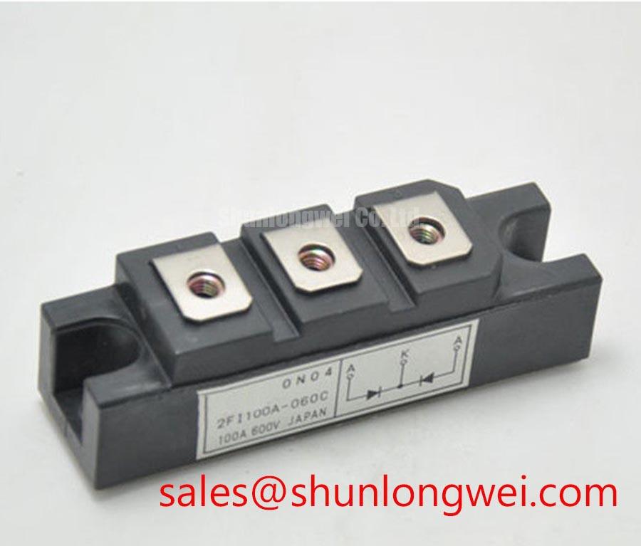
- Isolate the equipment, verify that stored energy has been discharged, and compare the installed module marking with 2FI100A-060C before disconnecting conductors.
- Check terminal alignment, fastener engagement, washer seating, and busbar support before disturbing the mounting assembly.
- Inspect the heatsink contact area, cooling passages, and thermal interface for contamination, displacement, or deterioration.
- Compare the gate connections and power-terminal arrangement with the equipment schematic before planning powered measurements.
The 2FI100A-060C is a Fuji Electric IGBT module with a specified voltage rating of 600 V, current rating of 100 A, and Fuji Power Module package designation. For equipment maintenance, these identification parameters establish the starting point; terminal geometry, cooling conditions, and protection behavior determine whether an installation is compatible.
| Product characteristic | Specification | Integration relevance |
|---|---|---|
| Model | 2FI100A-060C | Match the complete designation against the equipment parts record. |
| Manufacturer | Fuji Electric | Use model-specific manufacturer documentation for electrical and mechanical acceptance. |
| Rated voltage | 600 V — Official Specification | Evaluate switching peaks and operating conditions against the applicable rating conditions. |
| Rated current | 100 A — Official Specification | Assess actual loading together with cooling performance and temperature limits. |
| Package designation | Fuji Power Module | Check the mounting drawing and terminal arrangement. |
| Additional acceptance parameters | Consult Datasheet | Dimensions, pinout, tightening torque, gate limits, thermal characteristics, and short-circuit capability require model-specific documentation. |
Benchtop Waveform Tuning: Mitigating Mechanical and Electrical Stress on 2FI100A-060C
Check terminal screw engagement and washer seating with the busbar supported independently, so tightening does not pull a misaligned conductor into position. As a Design Consideration, thread engagement must suit the documented terminal geometry: a fastener that bottoms out can feel tight without establishing the intended contact pressure, while inadequate engagement can compromise retention. Select hardware from the approved assembly drawing rather than inferring dimensions from the package name.
Inspect the assembled joint for flat seating and unintended leverage. A stiff conductor, displaced spacer, or unsupported cable can transfer external loads into the terminal assembly during vibration and temperature changes. This is a general mechanical concern, not evidence of a particular internal leadframe or copper-joint construction in this model. Correct the external alignment before assigning an electrical symptom to internal module damage.
For waveform work, preserve the installed conductor geometry as far as practical. Moving a busbar to accommodate a probe can change the commutation loop and make the measurement less representative. Use appropriately rated differential measurement equipment, minimize probe-loop pickup, and document the probe location. Ringing that changes substantially with probe placement warrants investigation of the measurement arrangement before changes are made to the gate circuit.
As an Engineering Recommendation, compare terminal temperature trends under comparable load and ambient conditions. Local heating may involve contact resistance, conductor loading, cooling imbalance, or nearby heat sources; temperature alone does not identify the cause. With the assembly isolated, inspect contact surfaces and fastening records, then verify the corrected installation under controlled operating conditions.
Replacement evaluation should compare circuit configuration, terminal positions, mounting footprint, gate requirements, and thermal performance. The Fuji Electric 1MBI400L-060 is a separate product that can be included in a documented comparison, but it should not be treated as a verified direct replacement for 2FI100A-060C merely because both belong to the same manufacturer. Any substitution requires equipment-level compatibility approval.
Maintenance Note: Inspect cooling passages and thermal-interface condition at the equipment’s scheduled service intervals, and investigate rising terminal temperatures before adjusting fastening hardware.
2FI100A-060C Operational Boundaries: Evaluating Fault-Clearing Dynamics and Type-I/II Short Circuits
Trace the fault-detection path from the monitored power terminal through the gate-driver protection circuit to the gate-disable command. As a Design Consideration, a type-I short circuit generally describes turn-on into an existing fault, while a type-II event develops during conduction. These conditions place different demands on detection and interruption; neither establishes a model-specific withstand duration without the applicable short-circuit safe operating area specification.
Review detection blanking, sensing delay, isolation propagation, and gate discharge as one protection chain. Blanking should reject legitimate switching transients without hiding a developing fault. A generic microsecond target is not an acceptance limit for this module. Protection timing must remain within the documented device capability under the actual bus voltage, gate drive, and initial temperature conditions.
A staged soft turn-off is a Design Consideration when abrupt interruption would create excessive inductive overshoot. The driver must reduce fault current while controlling the voltage rise, without prolonging semiconductor stress beyond the permitted operating envelope. Its discharge profile, transition thresholds, and any clamp action are system-selected settings that require coordinated verification, not fixed characteristics of 2FI100A-060C.
Check complementary gate commands at the driver outputs rather than relying only on controller timing. Propagation differences, switching delay, and gate discharge behavior affect the interval between opposite switches conducting. Interlock logic should maintain the intended exclusion during startup, shutdown, supply disturbances, and protection recovery. Dead time is an equipment-level setting derived from these conditions, not a number inferred from the current rating.
As a Design Consideration, collector-to-gate coupling can disturb the off-state gate during rapid switching. Reverse-transfer capacitance and Miller-region charge are related but distinct quantities; capacitance is not itself a charge specification. Gate-return routing, driver sink capability, and clamp behavior should be assessed together. An active clamp is not a substitute for adequate voltage margin or coordinated fault interruption.
Where the equipment uses an optocoupler or digital isolator, examine its common-mode transient immunity alongside the observed switching transitions and local supply behavior. Erratic gate commands can originate in signal coupling, supply disturbance, or measurement pickup. Fuji Electric’s High-Speed Discrete IGBTs page provides manufacturer context for a separate device category; it does not establish this module’s gate-driver requirements or protection limits.
2FI100A-060C Thermal-Electrical Optimization: DC-Link Capacitance Bank Layout and Practical Tuning
Inspect the current path between the local DC-link capacitors and switching terminals before changing snubber components. As a Design Consideration, a compact outgoing and return path reduces commutation-loop inductance and its associated turn-off overshoot. Closely coupled conductors must still preserve the clearance and insulation requirements established for the complete equipment.
An Engineering Calculation can explain the measurement: switching peak voltage is approximately the DC-link voltage plus loop inductance multiplied by the rate of current change. This simplified relationship helps separate bus-voltage contribution from inductive overshoot, but distributed parasitics, recovery current, and clamp action affect the actual waveform. Establish acceptable margins using measured switching conditions and the documented device limits rather than a universal inductance target.
Choose snubber capacitance and damping from the observed oscillation and loss budget. Excess capacitance can increase switching-related current, while unsuitable damping can leave ringing unresolved or introduce additional heating. Evaluate capacitor pulse capability, connection inductance, and resistor dissipation together. If measurements change after relocating a capacitor or probe, distinguish the layout effect from the component-value effect.
Review the equipment schematic before assigning roles to associated semiconductors. The 2MBI200S-120 is another Fuji Electric module that may be considered in a separately specified converter stage; its product designation does not establish it as the front-end rectifier or auxiliary device in an installation using 2FI100A-060C. Engineers evaluating commercial string inverters or micro-grid energy-storage converters should verify the complete topology and operating envelope before considering either product.
As a Design Consideration, diode reverse recovery can influence commutation current and electromagnetic emissions where the documented circuit includes a recovery path. Recovery softness is meaningful only with its definition and test conditions; no model-specific softness factor is assigned here. Compare recovery-related waveforms under representative operating conditions, then assess emissions at equipment level. Fuji Electric’s SiC semiconductor information offers separate technology context, not proof of interchangeability or EMC compliance.
Evaluate pulse heating with the applicable transient thermal impedance and loss waveform, rather than heatsink temperature alone. Keep cooling passages clean, examine thermal-interface deterioration during planned outages, and investigate moisture or condensation before re-energization. The distributor article Unlocking Efficiency in Industrial Drives provides broader switching and thermal-design background; it is not a Fuji Electric specification for this module. After maintenance, verify stable temperatures and repeatable switching behavior under the equipment’s approved acceptance procedure.