Content last revised on September 10, 2026
Multi-Module Parallel Current Sharing & Positive Tempco Dynamic Balancing
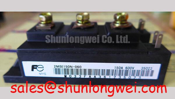
When deploying the Fuji Electric 2MBI150N-060 in high-capacity utility-scale solar conversion topologies, paralleling multiple half-bridge modules is standard practice to scale inverter phase currents beyond 300A. At this power level, static and dynamic current imbalances present severe risks to long-term reliability. Static current sharing depends directly on the collector-emitter saturation voltage (VCE(sat)), which is rated at a typical 2.3V and a maximum of 2.8V at nominal collector current. Because the N-series silicon exhibits a positive temperature coefficient at nominal and elevated operating currents, an IGBT carrying more current naturally heats up, increasing its internal resistance and shifting excess current to parallel sister modules. However, relying solely on this physical mechanism is insufficient to maintain safe operating margins during steep power ramp rates.
Dynamic balancing during turn-on and turn-off transitions requires strict layout symmetry. Asymmetrical loop inductances between the DC-link busbar and the module power terminals cause transient current crowding, driving one silicon die beyond its Safe Operating Area (SOA). To prevent this:
- Maintain matched gate-drive trace lengths across all paralleled modules, with trace inductance differences held below 5 nH.
- Implement discrete gate resistors (RG) for each individual gate terminal rather than driving paralleled gates from a single common resistor, preventing high-frequency parasitic ringing between modules.
- Ensure Kelvin emitter connections are decoupled from the main power return path to eliminate common-source emitter inductance feedback.
⚠️ Field Alert: During emergency field replacements of paralleled units, never mix different production lots without verifying forward voltage drop. Measure the diode forward voltage (VF) and VCE(sat) under test currents before mounting. When higher voltage headroom is required in legacy solar sub-inverter retrofits, engineers often cross-evaluate the higher-voltage rated 2MBI150F-120 to accommodate modified bus voltage levels.
| Parameter | Symbol | 2MBI150N-060 Specification | Field Diagnostic Limit |
|---|---|---|---|
| Collector-Emitter Voltage | VCES | 600V | Derate to 360V–400V for high-altitude PV links |
| Collector Saturation Voltage | VCE(sat) | 2.3V (typ) / 2.8V (max) | Reject if ΔVCE(sat) > 150mV across parallel set |
| Thermal Resistance (IGBT) | Rth(j-c) | 0.21°C/W | Baseplate dry contact increases value by >300% |
Cosmic Ray Robustness: Voltage Derating Curves across 2000m-4000m Altitudes
Utility-scale central and string solar installations are frequently situated in high-desert and mountainous regions between 2000 and 4000 meters above sea level. High-altitude operation drastically increases exposure to terrestrial cosmic ray neutrons, which directly elevates the risk of Single Event Burnout (SEB). Unlike thermal runaway or overcurrent degradation, SEB occurs instantaneously when a high-energy neutron collides with the silicon lattice within the high-field space charge region, generating localized current filaments that trigger catastrophic breakdown below the rated 600V breakdown threshold.
The failure rate, expressed in Failures in Time (FIT, 1 FIT = 1 failure per 109 component hours), scales exponentially with applied DC-bus voltage and altitude. At 3000 meters, atmospheric neutron flux is approximately 4 to 8 times higher than at sea level. To maintain inverter system reliability under 100 FIT per power module, standard engineering guidelines require operating the 2MBI150N-060 at a steady-state continuous DC-link voltage not exceeding 380V–400V.
High-side gate drive stability also demands proper bootstrap circuitry calculations in these extreme altitude operating conditions. Calculate the minimum bootstrap capacitance using:
Cboot ≥ (Qg + Ileak × ton) / ΔVboot
Where Qg represents the total gate charge required to switch the module, Ileak is the sum of driver quiescent and gate leakage currents, ton is the maximum duration of the high-side switch conduction state, and ΔVboot is the maximum allowable voltage ripple on the floating rail (typically ≤ 0.5V). When evaluating advanced converter topologies, engineers reference modern topologies found in Fuji Electric Discrete IGBT & SiC MOSFETs to benchmark cosmic ray robustness and gate charge profiles across high-density installations.
Evaluating Thermal Capacitance vs Heat Sink Time Constant under Surge Bursts
In 1500V multi-level solar inverter architectures (such as 3-level Neutral Point Clamped configurations), intermediate stages experience heavy thermal transients during grid-fault ride-through (GFRT) events, sudden cloud-edge irradiance spikes, and motor brake-chopper engagements. The module features an IGBT thermal resistance junction-to-case (Rth(j-c)) of 0.21°C/W. During short burst overloads lasting under 10 milliseconds, the heat sink remains thermally inactive due to its large thermal time constant (typically 10 to 60 seconds). All dissipated surge energy is absorbed locally by the silicon die and copper baseplate thermal capacitances.
Accurate transient thermal calculations rely on multi-stage RC network representations (Foster or Cauer models). For transient overload durations tp:
- For pulses where tp < 1 ms: Transient thermal impedance Zth(j-c) is governed entirely by the silicon die mass and internal solder layers.
- For pulses where 1 ms < tp < 100 ms: Heat flows through the direct bonded copper (DBC) ceramic substrate to the module baseplate.
- For pulses where tp > 1 s: The heat sink time constant begins to dictate the temperature gradient, requiring active cooling extraction.
💡 Pro Tip: Always follow exact thermal mounting protocols. Apply a uniform, 50-micron to 80-micron layer of high-conductivity thermal paste (minimum 3.0 W/m·K) across the module baseplate. Tighten mounting screws in a two-step cross pattern: first to 1.0 N·m, then to the final specified torque of 3.5 N·m to 4.5 N·m. Inadequate or excessive torque warps the internal ceramic substrate, causing localized hot spots and micro-fractures under repetitive power cycling. For standard field assessment procedures on damaged modules, consult the diagnostic methodologies outlined in the Field Engineer’s Handbook.
High dv/dt Cross-Conduction Shoot-Through Mitigation via Dedicated Miller Clamps
Modern solar inverters operate with rapid switching transitions to minimize switching losses. However, high turn-off dv/dt rates (exceeding 5 kV/μs) at the phase output node generate displacement currents through the collector-gate parasitic capacitance (Miller capacitance, Cres). This displacement current flows through the internal and external gate resistance, creating a spurious voltage rise across the gate-emitter terminals of the complementary off-state IGBT:
IMiller = Cres × (dv/dt)
If this induced transient voltage exceeds the gate threshold voltage (VGE(th), typically between 5.5V and 7.5V for the 2MBI150N-060), the off-state switch conducts momentarily while the opposite switch is active. This dynamic shoot-through causes localized current spikes, excessive thermal stress, and eventual gate insulation puncture.
Two primary hardware implementations prevent shoot-through failures in field installations:
- Negative Gate Bias: Supplying a negative turn-off rail (-5V to -15V) instead of a 0V turn-off level provides a wide noise margin that absorbs displacement currents without crossing the positive conduction threshold.
- Active Miller Clamping: Dedicated gate driver ICs monitor gate voltage during turn-off. When the gate potential drops below approximately 2.0V, an auxiliary internal low-impedance transistor shorts the gate to the negative rail or emitter, bypassing the external gate resistor entirely.
In dynamic braking and energy-dump sub-circuits across PV balance-of-plant hardware, integrating dedicated modules like Fuji Electric Brake Chopper IGBT Modules ensures robust overvoltage suppression, protecting the central switching array from severe inductive kickback during emergency shutoffs.