Content last revised on October 18, 2026
2MBI200L-060 Circuit Protection and Reliability: Calibrating Main Terminal Mechanical Stress
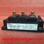
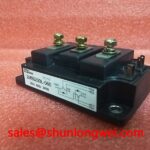
Before energizing a replacement module, I check the main terminal threads, washer seating, busbar alignment, and enclosure clearance with the DC link isolated. The 2MBI200L-060 is a Fuji Electric IGBT module rated at 600.0 V and 200.0 A, with a Fuji Power Module housing. Those ratings identify the electrical class of the component; they do not remove the need to verify the mechanical interface inside the traction inverter or braking chopper.
On a forklift or electric material handling drive, a rigid copper busbar can transmit vibration directly into the module terminals. A terminal that is pulled sideways during assembly can place levering stress on the internal copper joins. Thermal cycling then repeatedly expands and contracts the busbar, terminal hardware, and mounting base. The result may appear later as intermittent switching, increased local heating, or an open circuit that only occurs after the enclosure reaches operating temperature. The inspection target is therefore not only the screw head. It is the complete force path from the external busbar through the washer and terminal into the module body.
Place the busbar over the module without tightening it and check whether the holes align naturally. If the bar must be forced into position, loosen the upstream support points and correct the mechanical alignment before applying terminal pressure. The busbar should not twist the terminal, lift one corner of the washer, or press against the molded housing. Keep conductive hardware clear of adjacent terminals and use the original insulation barriers or equivalent system-approved barriers where the enclosure design requires them.
The correct thread engagement is determined by the terminal hardware, screw specification, washer arrangement, and assembly drawing for the equipment. It should be sufficient for stable clamping without allowing the screw to bottom out or transfer excessive force into the module body. A bottomed screw can produce a false feeling of tightness while leaving the busbar inadequately clamped. A screw that is too long can also interfere with internal construction. Torque must follow the applicable Fuji documentation or the equipment manufacturer’s assembly specification rather than an assumed value.
⚠️ Field Alert: Do not use the terminal screw to pull a misaligned busbar into position; correct the busbar support and apply the specified tightening sequence with the DC link fully discharged.
During a field replacement, record the original busbar orientation, washer order, cable routing, and support points before removal. After installation, inspect for copper marks, displaced washers, cracked insulation, or terminal rotation. A cold resistance check across the disconnected power paths can support comparison with a known-good assembly, but it should be treated as a screening measurement rather than proof of dynamic health. Gate terminals should remain protected from accidental static discharge, and the control connector should be inspected for bent contacts or contamination before the first powered test.
For a potential same-family service comparison, engineers may review the 2MBI50J-060 as a separate Fuji Electric module listing. It should not be treated as an automatic substitute. Voltage class, current demand, terminal geometry, gate-drive behavior, thermal interface, protection settings, and mechanical envelope must all match the original equipment design before any replacement decision is made.
Preventing Spurious Faults: Evaluating Thermal Capacitance and Heat-Sink Response
Heavy pulsed overloads in a regenerative braking chopper can make a module appear electrically intermittent when the real issue is accumulated thermal energy in the junction, case, thermal interface, and heat sink. The 600.0 V, 200.0 A ratings of the 2MBI200L-060 are official device ratings, while the permissible operating point in a forklift traction inverter depends on switching frequency, pulse duration, duty cycle, cooling conditions, current waveform, and the thermal path established by the equipment.
During regenerative braking, the chopper directs DC-link energy into a braking resistor. The resistor absorbs energy as heat, while the IGBT and its freewheeling path carry the switching current. A short overload may not immediately produce a high case temperature because the heat sink has thermal mass. The semiconductor junction, however, responds faster than the external heat sink. A service engineer should therefore compare the pulse profile with the complete transient thermal model instead of judging safety from a brief surface-temperature reading.
A multi-RC thermal model represents the junction-to-case path as several thermal storage and transfer elements. In practical terms, each element describes a different response speed: the junction reacts first, the case follows, and the heat sink responds more slowly. To estimate peak junction temperature, integrate the real conduction and switching losses over the pulse sequence and combine the resulting transient response with the measured case temperature. The calculation requires the manufacturer’s thermal impedance curves and the actual mounting condition. It should not be replaced by a single steady-state resistance value when the braking event is highly pulsed.
When a drive reports an overcurrent or overtemperature fault after repeated braking events, capture the event timing, DC-link voltage, phase current, chopper current, gate command, and case temperature. A fault that arrives only after a sequence of stops may point toward thermal accumulation, braking resistor limitations, airflow changes, or protection coordination. A fault that appears at the first switching edge requires a different investigation, including gate-drive integrity, commutation layout, overshoot, and current-sensor behavior. These observations help separate a thermal transient from a control or power-loop disturbance without assigning one symptom to one cause automatically.
The freewheeling diode path also deserves attention. Reverse recovery creates a current transient when the conducting diode is forced off. Its interaction with stray inductance can raise voltage across the switching loop and generate conducted or radiated interference. The resulting disturbance may couple into the gate-drive return, current feedback, brake resistor control, or vehicle communication wiring. Use a properly compensated differential probe and a short measurement loop when capturing switching nodes. A long oscilloscope ground lead can create ringing that is not present in the equipment.
Snubber selection is a system-level engineering recommendation. The network must be selected from measured overshoot, switching energy, pulse repetition, capacitor characteristics, resistor dissipation, and available clearance. A snubber that is too aggressive can increase switching loss, while one that is too weak may leave the semiconductor exposed to excessive transient stress. The engineer should verify the result at the intended DC-link voltage and temperature, with the actual busbar, braking resistor, gate driver, and enclosure installed.
Fuji Electric’s information on brake chopper IGBT modules provides useful context for evaluating chopper switching functions and application relationships. It should be read alongside the device-specific documentation and the inverter maker’s protection settings. For a related device family, the Fuji Electric RC-IGBT module information can help engineers distinguish integrated reverse-conduction concepts from the topology used in the equipment under repair.
Positive temperature coefficient behavior can assist static current sharing when multiple parallel IGBT paths are designed correctly, but it does not guarantee equal dynamic sharing. Small differences in gate-loop inductance, emitter wiring, threshold behavior, stray inductance, and switching timing can cause one device to take more current during turn-on or turn-off. When parallel modules are present, use symmetrical power and gate-drive paths, matching mechanical interfaces, and independent temperature and waveform checks. The final balance must be verified in the assembled inverter rather than inferred from the nominal current rating alone.
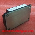
The thermal interface material is part of the electrical reliability chain because uneven contact raises case temperature and changes the transient margin. Remove old compound without scoring the baseplate or heat sink, inspect both surfaces for burrs and distortion, and apply only the amount specified by the equipment or thermal-interface supplier. Excess compound can create a thick, uneven layer; insufficient coverage can leave dry regions. Tighten the mounting hardware in the specified sequence so the baseplate seats evenly and does not bow against the heat sink.
2MBI200L-060 DC-Bus Protection and Low-Inductance Busbar Design
In the DC bus, the most useful first check is to trace the complete commutation loop from the local DC-link capacitor to the IGBT, return path, and freewheeling diode. The loop should be compact, mechanically supported, and arranged to minimize opposing-current separation. During turn-off, stray inductance combines with current slew rate to create an additional voltage component; in engineering terms, the peak voltage rises with the product of loop inductance and di/dt. The system designer must compare the measured peak with the permitted switching margin at the actual operating condition.
A laminated busbar can reduce loop area by placing the positive and negative conductors close together with a controlled dielectric layer. The benefit comes from field cancellation and reduced parasitic inductance, not from the material name alone. The layout must preserve insulation distance, avoid sharp edges near the module housing, and provide mechanical support so vibration does not change the conductor spacing. Keep the high-current commutation path separate from sensitive gate and current-feedback wiring, and route control returns to the intended reference point rather than allowing them to share an uncontrolled power-current path.
During troubleshooting, inspect the DC-link capacitor connection, busbar overlaps, flexible cable transitions, and terminal surfaces as one network. A loose capacitor connection can produce the same type of switching disturbance as an inadequately supported busbar. Check for darkened copper, localized discoloration, melted insulation, or witness marks around the terminal washers. If the fault is load-dependent, capture the switching waveform at several current levels and compare the ringing frequency and peak amplitude. A change in ringing with cable position or enclosure assembly often points toward parasitic geometry rather than a simple semiconductor failure.
Snubber capacitors should be placed according to the measured commutation loop and the voltage transient that requires control. Their capacitance, equivalent series resistance, pulse-current capability, and physical connection length all influence the result. The capacitor must be rated for the repetitive waveform and mounted so that its own connection does not create another large inductive loop. Select the associated damping element from measured ringing and loss, then confirm component temperature during the complete duty cycle.
For a regenerative braking system, the DC-link capacitor, chopper module, braking resistor, and resistor switching frequency must be considered together. The resistor absorbs braking energy, but the module still experiences the switching loss associated with controlling that energy. If the resistor value, cooling, or control threshold changes during a retrofit, the current pulse and thermal profile may also change. Verify the complete braking sequence, including acceleration recovery, repeated stops, and any DC-link overvoltage intervention.
When a front-end rectifier or complementary power stage is being assessed, engineers may review the 2MBI50-120 as a separate related component. Its presence in a system does not establish electrical interchangeability with the 2MBI200L-060. The rectifier voltage class, current path, switching topology, control method, heat-sink arrangement, and protection coordination must be evaluated independently.
The oscilloscope connection should be planned before the high-voltage test. Use probes and accessories rated for the measurement category, maintain the required clearance around exposed conductors, and avoid attaching measurement clips to unsupported busbar sections. Confirm that the DC-link discharge circuit has reached the equipment’s safe service condition before repositioning probes or removing the module. A known-good waveform from the same drive is often more useful than a generic waveform because it preserves the actual gate driver, busbar, capacitor, and load relationships.
For broader service planning, the Power Electronics Masterclass offers a wider reference point for IGBT selection, switching stress, and system reliability assessment. The replacement decision for the 2MBI200L-060 should still be made against the original equipment’s electrical ratings, mechanical arrangement, thermal path, gate-drive requirements, and measured switching behavior.
After the mechanical installation and low-voltage control checks are complete, bring the traction inverter up through a controlled test sequence. Confirm gate timing, current direction, braking command response, DC-link behavior, and temperature rise before returning the vehicle to repeated duty. For forklift traction equipment, compatibility should be assessed against the complete low-voltage drive system, including motor characteristics, regenerative braking limits, battery condition, cooling airflow, and controller protection logic.