

Content last revised on October 7, 2026
Active Miller Clamp Implementation & Parasitic Capacitive Turn-On Prevention
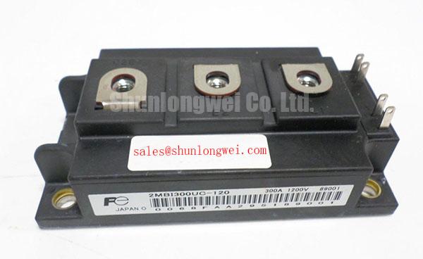
With the industrial inverter welder isolated and its DC link confirmed discharged, check the 2MBI300UC-120 gate-to-emitter paths for unexpected shorts before reconnecting the driver. A cold multimeter check is an initial screen, not proof that the module will switch correctly under load. Inspect the gate wiring and nearby terminals for looseness, heat discoloration, or conductive debris, then compare the driver connections with the machine schematic.
The supplied product specifications identify the Fuji Electric 2MBI300UC-120 as an IGBT module with a 1,200 V rated voltage and 300 A rated current (Official Specification provided for this product). Because a voltage error has direct consequences for replacement decisions, verify those ratings against the original equipment documentation and the identification on the unit being removed before energizing the welder. The ratings alone do not establish the allowable DC-link voltage, switching conditions, or short-circuit capability.
In a bridge leg, rapid voltage change at one switch can couple through the opposing switch’s gate-to-collector capacitance and raise its gate voltage. If the opposing device turns on unintentionally, the fault can resemble a driver failure or a power-stage short. As a Design Consideration, an active Miller clamp can provide a low-impedance path from gate to emitter while the device is commanded off. Its suitability depends on the driver circuit, actual gate waveform, module connections, and measured switching behavior; a negative off-state gate bias is likewise a system-level choice, not a specified requirement for this module.
For a medium-frequency induction heating supply, inspect the physical return path as well as the schematic. Long gate leads, shared power-current conductors, and a poorly placed clamp can undermine an otherwise sound driver design. Probe the gate-to-emitter voltage during controlled switching and compare it with the command signal and the opposing switch’s voltage transition. The Fuji Electric V-Series IGBT Application Manual provides application-level guidance on gate driving and switching behavior; its examples should not be mistaken for missing device-specific limits for the 2MBI300UC-120.
Kelvin Emitter Connection & Parasitic Inductance Minimization in High-Speed Switching
Trace the emitter connection from the module to the gate driver before changing a suspected power device. A dedicated auxiliary emitter connection, where one is provided and confirmed by the applicable terminal drawing, can keep part of the high-current emitter voltage drop out of the driver’s reference path. Do not assume that the 2MBI300UC-120 has a Kelvin emitter terminal from its model name or module designation alone. Identify every terminal from the documentation for the exact installed unit.
As a Design Consideration, keep the verified driver return close to its associated gate path and minimize the high-current commutation loop. These measures can reduce unwanted gate-voltage disturbance and turn-off overshoot, but the layout still needs validation in the assembled welder or heating supply. If the gate trace shows ringing, compare the waveform at the driver output with a measurement referenced at the module’s verified gate and emitter terminals. A difference may point toward wiring or connection impedance rather than an incorrect driver command. Use measurement methods appropriate for the circuit’s voltage and isolation requirements.
When evaluating a replacement, physical fit and current rating are only the first checks. The linked 6MBI300U-120 is a separate Fuji Electric model to compare, not a confirmed drop-in substitute. Check circuit topology, terminal assignment, mounting dimensions, gate-drive requirements, and the equipment’s documented voltage limits before considering a cross-model change.
A fast semiconductor fuse also needs coordination at the system level. Its published clearing characteristics must be assessed against the available fault current and the applicable device limits; a matching current label does not demonstrate protection of the IGBT during a short circuit. The Field Engineer’s Handbook offers a practical reference for organizing fault inspection and test observations when operating margins or the original failure mechanism remain uncertain.
Thermal Time Constants (tau_i) and Peak Junction Temperature Margin Calculation
After a pulsed-overload shutdown, record what the equipment actually did: load duration, cooling operation, case or heatsink temperature, and the protection signal that stopped switching. A cool heatsink measured after shutdown does not establish the junction temperature reached during the pulse. Conversely, a hot mounting surface does not, by itself, identify a damaged module. Check for uneven mounting pressure, contamination on the contact surfaces, and evidence that the cooling path was obstructed.
The supplied 300 A current rating (Official Specification provided for this product) is not a standalone pulsed-current allowance. Estimating peak junction temperature requires device-specific transient thermal impedance data, a defensible estimate of conduction and switching losses, the measured operating pulse, and the case-temperature condition. A multi-RC thermal model can represent the changing junction-to-case response over time, but no thermal time constants or transient impedance values have been supplied here. It would therefore be unsound to calculate a numerical peak temperature or overload margin for this product page.
As a Design Consideration, compare the reconstructed duty cycle with the exact manufacturer thermal data before authorizing repeated high-power tests. In a welder, capture the relationship between output-current pulses and temperature rise; in an induction heating supply, include the operating pattern of the load and cooling system. If recorded temperatures change after module service, check the mounting interface and airflow or liquid-cooling path before attributing the change solely to semiconductor losses.
⚠️ Field Alert: Do not reuse an unverified mounting torque or apply a thick layer of thermal compound; confirm the fastener and interface instructions for the installed module before reassembly.
High-Speed Fault Management: V_CE(sat) Desaturation Sensing Circuitry
When a welder trips as current rises, read the driver fault indication before resetting it. A desaturation circuit monitors collector-to-emitter voltage while an IGBT is commanded on; an abnormal rise can indicate that the device is no longer conducting as expected. The same indication can also arise from sensing-path faults, timing errors, or switching transients. Check the fault record, driver supply, sense connection, and gate command together rather than treating the alarm as a diagnosis of the module alone.
Type-I and type-II short-circuit events place different demands on the power stage, depending on whether the fault is present at turn-on or develops while the device is already conducting. Desaturation blanking, detection delay, and turn-off behavior must be coordinated with the exact IGBT’s published short-circuit limits and the assembled circuit. No device-specific detection time or short-circuit safe operating area has been supplied for the 2MBI300UC-120, so a fixed microsecond target cannot responsibly be assigned here. As a Design Consideration, controlled turn-off may help limit inductive overvoltage after fault detection, but its waveform and peak voltage require testing in the equipment.
Keep the sense wiring clear of the high-current switching path where the equipment layout permits, and inspect its diode, resistor, and return connections against the driver schematic. During a supervised test, correlate the desaturation indication with collector-to-emitter and gate-to-emitter waveforms using suitable isolated instrumentation. Confirm that the resulting peak voltage stays within the verified device and system limits. For equipment using another Fuji Electric power-stage part, 2MBI450UE-120 can be reviewed as a separate topology reference; its presence in a design would not establish electrical compatibility or fault-setting equivalence with this module.