Content last revised on October 18, 2026
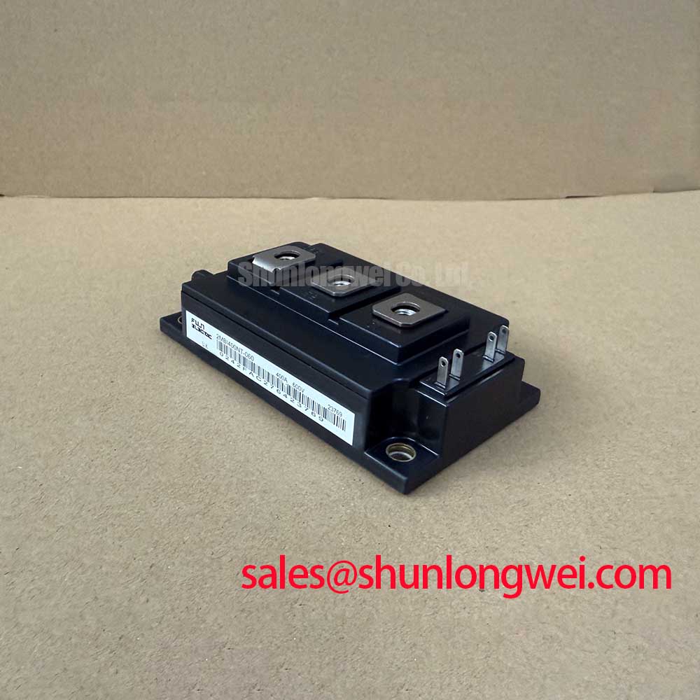
Fuji Electric 2MBI400NT-060-02 Ratings and Diagnostic Checks
With the DC link discharged and verified de-energized, isolate the power terminals before comparing collector-emitter and gate-emitter resistance readings against the circuit diagram and a known-good channel. For the Fuji Electric 2MBI400NT-060-02, the official maximum ratings include 600 V collector-emitter voltage and a 400 A collector-current rating under the specified datasheet conditions. Cold resistance checks can identify suspicious conduction paths, but they cannot establish switching performance or remaining service life.
The official specification also states 2500 V AC isolation voltage for 1 minute, a low stray inductance module structure, and saturation-voltage classification for easier parallel connection. That classification is not a numerical saturation-voltage specification or permission to parallel unmatched assemblies. For terminal assignments, dimensions, mounting requirements, and rating conditions, consult the manufacturer datasheet corresponding to the complete 2MBI400NT-060-02 suffix before approving a replacement.
Field Diagnostics & Commissioning: Sizing Braking Resistors and Chopper Stages in 2MBI400NT-060-02 Topologies
Trace the braking branch on the schematic before attributing a deceleration overvoltage trip to the module. Establish whether the brake switch is internal to the power assembly or belongs to a separate chopper stage. As a Design Consideration, regenerative energy returns to the DC link during motor deceleration; a chopper-controlled resistor dissipates the portion that the supply or another energy path cannot absorb. An open resistor, interrupted thermal interlock, defective switching path, or missing command can produce similar symptoms.
Check resistor continuity with parallel paths disconnected, inspect its terminations, and examine the chopper command alongside the DC-link waveform during a controlled commissioning run. A resistor that passes a cold continuity test can still have an intermittent connection or inadequate repetitive-duty capability. Record the deceleration profile, load condition, starting bus voltage, and cooling state so the measurements describe a repeatable operating event rather than an isolated trip.
Engineering Recommendation: select braking resistance from the controller’s permitted resistance range and the chopper’s current capability, then assess pulse energy and average dissipation against the machine’s stopping cycle. A lower resistance increases braking current; a higher resistance can reduce energy-removal capability. The final selection belongs to the complete drive design, including protective coordination and resistor temperature limits, not to the module’s 400 A rating alone.
Keep resistor heat away from module cooling-air inlets and temperature-sensitive wiring. Route brake-current conductors to limit loop area while preserving the equipment’s required clearance and creepage distances. During replacement assessment, the related 2MBI150NC-060-10 should be treated as a separate comparison candidate, not an established direct replacement; electrical ratings, terminal geometry, drive requirements, and thermal capability require an explicit compatibility review.
2MBI400NT-060-02 Thermal-Electrical Optimization: Oscilloscope Waveform Verification
Capture collector-emitter voltage and gate-emitter voltage together when assessing a legacy driver connected to the 2MBI400NT-060-02. Use suitably rated differential probes and a measurement arrangement with minimal pickup. As a Design Consideration, apparent gate ringing can originate in the probing loop, so check measurement integrity before changing gate resistance. Compare switching events under controlled current, bus voltage, and temperature conditions.
Where the driver provides separate turn-on and turn-off resistance paths, evaluate them independently. Increasing turn-on resistance can moderate current commutation but can also increase switching loss. Changing turn-off resistance affects voltage overshoot, transition duration, and susceptibility to unwanted gate movement. Engineering Recommendation: retain the driver’s intended protection functions and adjust damping only through a documented validation process that checks both switching waveforms and thermal behavior.
Contain external commutation-loop inductance by keeping the relevant DC-link capacitor, bus connections, and switching terminals electrically close, subject to mechanical and insulation requirements. The module’s specified low stray inductance does not remove inductance from external conductors. Position a snubber capacitor according to the actual transient-current path rather than simply placing it near the enclosure wall; its effectiveness depends on the connection loop as well as its electrical characteristics.
Inspect the driver supply and isolation stage when gate disturbances coincide with fast collector-voltage transitions. As a Design Consideration, an optocoupler or digital isolator must maintain correct output behavior under the common-mode transients present in the assembled drive. Check the installed isolator’s documented capability, gate-return routing, and local decoupling before blaming the power module. General background on interconnect-related parasitics is available in the flip-chip packaging reference; it does not establish that this Fuji module uses flip-chip or copper-pillar construction.
2MBI400NT-060-02 Thermal-Electrical Optimization: Preventing Terminal Overheating
Measure each suspect bolted connection with a four-wire micro-ohmmeter after isolating the assembly and accounting for parallel conduction paths. Place the sense leads so the measurement includes the intended contact interface rather than an uncontrolled length of busbar. As a Design Consideration, compare readings between equivalent joints at similar temperatures and against established equipment acceptance criteria; a universal contact-resistance threshold is not a manufacturer specification for this module.
Thermographic inspection becomes useful when the load, airflow, and operating duration are recorded alongside the image. Compare equivalent terminals and inspect the temperature gradient through the conductor and connection. A localized hot region can justify closer examination of joint pressure, surface condition, alignment, or conductor loading, but the image alone does not identify a single cause. Reflective metal surfaces also require careful interpretation of apparent temperature.
Field Alert: Apply the specified terminal and mounting torques with a calibrated tool, and never use bolt tightening to pull a misaligned busbar into position.
Check that terminal hardware seats correctly and that connected conductors do not impose bending loads on the module. Engineering Recommendation: inspect the heatsink contact surface and restore the thermal interface according to the module and equipment assembly instructions whenever the module is removed. The discussion in The Advanced Thermal Management Revolution provides broader thermal-path context, without establishing the internal substrate or cooling construction of this part.
The specified 2500 V AC, 1-minute isolation rating must not be converted into an installation clearance rule or an unrestricted field-test instruction. Preserve the original terminal spacing, barriers, and conductor routing. For equipment exposed to pressure changes or contamination, insulation coordination should follow the applicable equipment requirements and environmental assessment, rather than assumptions drawn from the isolation test value.
2MBI400NT-060-02 Thermal-Electrical Optimization: Diode Recovery and Commutation Tuning
Observe commutation current together with collector-emitter voltage when investigating ringing associated with the freewheeling path. As a Design Consideration, reverse-recovery behavior depends on operating current, temperature, and the imposed commutation rate. A sharp recovery transition can excite the external power loop, but oscillation amplitude also depends on bus geometry, capacitance, and measurement technique. Do not assign a numerical softness factor or recovery-current limit without the applicable device characterization.
Where turn-on gate resistance controls the opposing switch’s commutation rate, assess whether additional damping reduces recovery-related stress without creating unacceptable switching loss. An RC snubber is another system-level option, but its resistance, capacitance, pulse loading, and physical placement should follow measured ringing and component stress. Engineering Recommendation: compare voltage overshoot, current recovery, driver behavior, and thermal response together rather than optimizing a single waveform feature.
For a compatibility review involving high-speed rail or heavy-freight locomotive traction-inverter equipment, establish the subsystem voltage, insulation requirements, switching duty, and applicable qualification requirements before considering this 600 V IGBT module. That example does not establish railway approval or suitability. Environmental reliability questions, including altitude-related effects, belong to the equipment assessment and manufacturer-supported reliability evidence rather than a presumed capability of the part number.
After any gate-network or snubber change, repeat the relevant operating transitions and check protection behavior as well as emissions-sensitive ringing. Record the installed component values, test conditions, and waveform references in the service record. Module-level damping changes do not establish equipment EMC compliance; acceptance depends on the assembled system’s applicable verification procedure.