Content last revised on October 5, 2026
Benchtop Waveform Tuning: Symmetrical Busbar Geometry for 6MBI150U4B-120
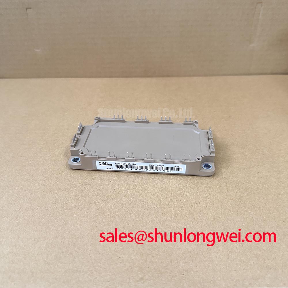
With the DC link discharged and isolated, compare the cold terminal measurements and package markings of the removed module against the equipment documentation before connecting a gate driver. The supplied product data identifies the 6MBI150U4B-120 as a Fuji Electric IGBT Module with a 1200 V voltage rating and 150 A current rating (Official Specification in the supplied product data). The voltage must be reconciled with the original Fuji Electric datasheet and the equipment parts list before energization; a model-number suffix is not a substitute for a verified voltage rating.
For a drive repair, the useful comparison is between the existing power stage and the documented device, not between headline current ratings alone. Confirm the terminal arrangement, mounting footprint, gate connections, diode arrangement, cooling interface and applicable test conditions for the current rating. If the original documentation is unavailable, leave those characteristics unconfirmed rather than inferring them from the module name.
Busbar symmetry matters when parallel current paths or multiple switching positions must behave alike. As a Design Consideration, keep corresponding power paths and gate-loop routing comparable to reduce differences in stray inductance. Then capture turn-on and turn-off waveforms at the operating conditions that impose the greatest electrical stress. A positive temperature coefficient of on-state voltage can assist static current sharing in an appropriately characterized arrangement, but its presence and operating range should be checked in the manufacturer’s characteristic curves; it cannot correct unequal switching transients.
When examining a turn-off spike, compare the measured collector-emitter peak with the verified device rating while recording DC-link voltage and current. Review busbar geometry, gate-return routing and measurement-probe placement before changing gate resistance. For a heavy-duty variable frequency AC motor drive under compatibility review, long motor cables add a separate concern: reflected-wave voltage at the motor terminals depends on cable impedance, edge speed and termination. Measure it at the motor end where possible rather than treating a DC-link measurement as proof of acceptable motor insulation stress.
💡 Pro Tip: Keep corresponding busbar paths symmetrical to limit turn-off overshoot, then confirm the remaining voltage margin with switching waveforms measured on the assembled drive.
A sourcing comparison with 6MBI300U-120 should therefore start with verified voltage rating, circuit configuration, terminal map and mechanical fit. Its different model designation does not establish interchangeability with 6MBI150U4B-120.
Field Diagnostics and Commissioning: Braking Chopper Operation in Drive Topologies
Trace the braking path on the drive schematic before assigning any braking function to this module. A regenerative deceleration event can raise DC-link voltage, while a braking chopper, when present, switches energy into a resistor selected for the drive’s braking duty. The supplied product data identifies 6MBI150U4B-120 as an IGBT module but does not establish that it contains a dedicated braking chopper or specify an internal resistor. Confirm which devices actually form the inverter and braking paths in the equipment being repaired.
Fuji Electric’s brake chopper IGBT module information illustrates why topology must be identified explicitly: a braking function depends on the circuit and its control, not on an IGBT label alone. During commissioning, record DC-link behavior during a controlled deceleration, inspect the chopper command against the resistor current, and compare both with the drive manufacturer’s service limits. Resistor suitability depends on the actual stopping energy, repetition rate, cooling and protection scheme; the IGBT’s current rating alone cannot establish it.
In a complementary switching leg, an interlock should prevent simultaneous conduction. As a Design Consideration, check the driver’s dead-time behavior at the gate terminals under representative temperature and load conditions. Gate-command timing by itself can miss switching delays and unintended turn-on associated with Miller coupling. Route the gate drive and its return as a controlled pair, inspect the measured off-state gate waveform, and let the system’s tested switching behavior determine any adjustment to interlock timing or damping.
When investigating an unexpected DC-link rise, separate braking-path evidence from inverter-leg evidence. Check whether the controller requested braking, whether the chopper switched, and whether the resistor path carried current. A missing event at one point in that sequence narrows the investigation but does not, by itself, identify a failed module. In a topology that uses an additional power stage, 2MBI150UC-120 can be examined as a separate device candidate; its role and compatibility require the same schematic and datasheet checks.
Fuji Electric also describes RC-IGBT modules as a distinct product grouping. That distinction is relevant when reading an existing schematic: do not transfer an internal circuit assumption from another module family to the 6MBI150U4B-120 without its exact circuit diagram.
Benchtop Waveform Tuning: DC-Bus Voltage Headroom for 6MBI150U4B-120
Read the highest captured collector-emitter voltage at the module terminals, not just the nominal DC-bus setting, when assessing voltage headroom. The supplied 1200 V rating (Official Specification in the supplied product data) is the stated boundary for this assessment, subject to confirmation against the original manufacturer documentation. Switching-loop inductance can add an overshoot during turn-off, so the system engineer should assess the measured peak against the verified rating across the intended operating range.
For troubleshooting, first establish a repeatable waveform with an appropriate high-voltage measurement setup. Compare the affected switching position with a known-good position where the circuit permits, and correlate overshoot with current, gate behavior and DC-link level. Ringing may reflect several interacting conditions, including power-loop inductance, gate-loop coupling and probe setup. Change one layout or drive variable at a time and retain the before-and-after traces; a cleaner-looking waveform at a single operating point does not establish adequate margin throughout the duty cycle.
Altitude and radiation-related failure mechanisms require a different level of evidence from ordinary bench waveform checks. As a Design Consideration, an elevated-altitude installation may warrant review of the manufacturer’s application guidance and the equipment’s voltage derating policy. The supplied product data provides no device-specific single-event burnout characterization, neutron-flux assessment or failure-in-time figure, so no quantitative altitude limit, FIT rate or lifetime prediction follows from the 1200 V rating. Keep that environmental review separate from the immediately testable question of switching-voltage headroom.
For gate-loop and switching-physics context during fault isolation, The Ultimate IGBT Knowledge Base provides background reading. The acceptance decision for this particular repair still rests on the correct module documentation and measurements from the assembled drive.
Benchtop Waveform Tuning: Baseplate Thermal Interface Control for 6MBI150U4B-120
Inspect the heatsink contact area and the module’s mounting surface before applying thermal interface material. Remove contamination without damaging either surface, and compare their flatness and mounting-hole alignment with the equipment’s mechanical requirements. The supplied specification identifies a Module package but gives no baseplate dimensions, screw size, torque or specified grease thickness. Obtain those details from the applicable Fuji Electric drawing and drive assembly instructions rather than treating a general workshop value as a module requirement.
As a Design Consideration, apply thermal interface material evenly enough to fill surface irregularities without creating an uncontrolled thick layer. Mounting pressure, material behavior and surface condition determine the resulting bond line. Tighten fasteners in the sequence specified for the assembly, bringing the module into contact progressively; do not use screw force to pull a visibly misaligned heatsink into position. If the original assembly used a defined interface material or mounting procedure, preserve that specification when evaluating a replacement.
After mounting, monitor case or heatsink temperature alongside current and switching conditions during a controlled run. An unexpectedly large temperature difference between comparable drive positions may warrant checks of cooling flow, interface coverage, fastener seating and electrical loss. It is not proof of a single thermal-interface fault. If electrical waveforms and mechanical contact have both been documented, the maintenance record can distinguish a cooling problem from excess switching stress without assigning an unsupported lifetime estimate to the module.