Content last revised on September 27, 2026
Benchtop Waveform Tuning: Mitigating Stress via Baseplate Convexity Compensation and Screw-On SKM200GAL173D
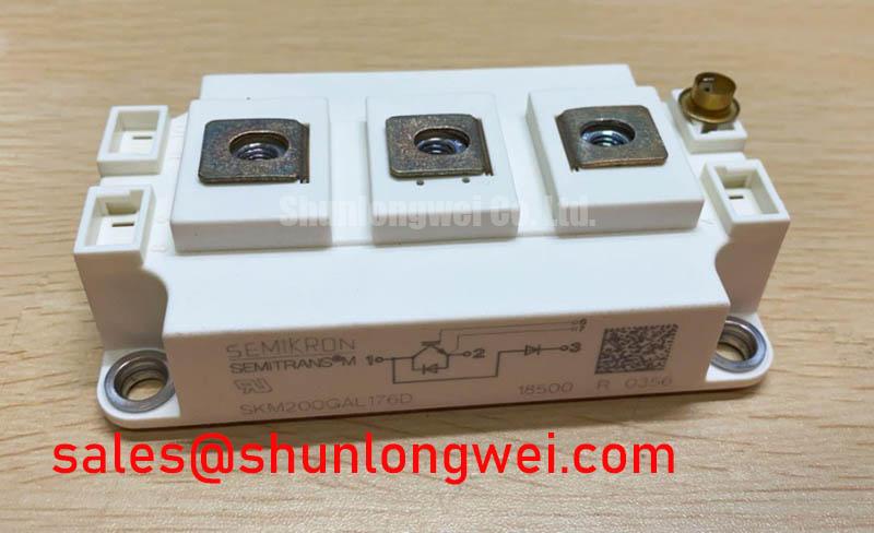
Check the terminal markings on the SKM200GAL173D against the equipment schematic before placing meter probes on the unpowered module. Record cold-state diode-mode readings in both probe directions across each identified power path, then compare them with a documented reference taken under similar conditions. A difference warrants closer examination; a diode-mode reading alone does not establish whether the module will behave correctly under switching load.
The confirmed identity checks are 1700 V rated voltage, 200 A rated current, and a Semitrans package (Official Specifications). Those ratings do not state an allowable surge-current waveform, a recovery interval after an overload, or an insulation test voltage. Before any surge or withstand test, obtain the applicable manufacturer documentation and follow the equipment’s isolation procedure. The broader Semikron-Danfoss SEMITRANS product information provides package-family context, but package-family information should not be treated as an unverified limit for this part number.
For a mounted unit, inspect the baseplate and heatsink contact surfaces before interpreting temperature or switching-waveform results. As a Design Consideration, an uneven mounting surface, trapped air, or excessive thermal interface material can impair heat transfer. Use the module-specific mounting instructions to determine material application and screw torque; tighten fasteners in the specified sequence rather than attempting to flatten the package with one screw. After assembly, compare case-temperature trends at comparable loads. A changed trend may justify checking contact quality, cooling conditions, and current distribution before attributing it to the semiconductor.
Waveform tuning belongs on the assembled power stage. Use suitably rated, isolated measurement equipment to observe turn-off voltage overshoot and gate behavior at representative operating points. Keep the commutation path compact to limit parasitic inductance, then verify measured peaks against the DC-link conditions and the module’s confirmed voltage boundary. An apparently quiet no-load trace cannot establish adequate margin during a demanding operating transition.
SKM200GAL173D Operational Boundaries: Evaluating Multi-Module Parallel Current Sharing Limits
Before planning a parallel bank, map every power and gate terminal from the exact SKM200GAL173D connection drawing. Do not infer terminal positions from the Semitrans package name. With the equipment isolated, check the proposed busbar arrangement for comparable path geometry, secure fastening, and the creepage and clearance required by the complete assembly. Mechanical support also matters where vibration could loosen a connection; the applicable fastening specification must come from the hardware and equipment documentation.
Parallel modules need separate checks for static and dynamic sharing. As a Design Consideration, a positive temperature coefficient of on-state voltage can assist static current balancing in an operating region where that behavior is established. It is not a substitute for the model’s temperature-dependent curves or for measurements across the intended load range. Measure branch currents under controlled conditions and compare their trends as temperatures settle; a single room-temperature meter reading cannot characterize hot operating balance.
Dynamic sharing depends on the gate-drive and power-loop paths during each transition. Route corresponding gate connections symmetrically and assess the measured gate and collector waveforms together. Unequal lead impedance or commutation-loop inductance can alter switching timing even when static branch currents appear close. The driver settings, switching conditions, and acceptable imbalance remain system-determined and should be checked against the manufacturer’s detailed data before parallel operation is approved.
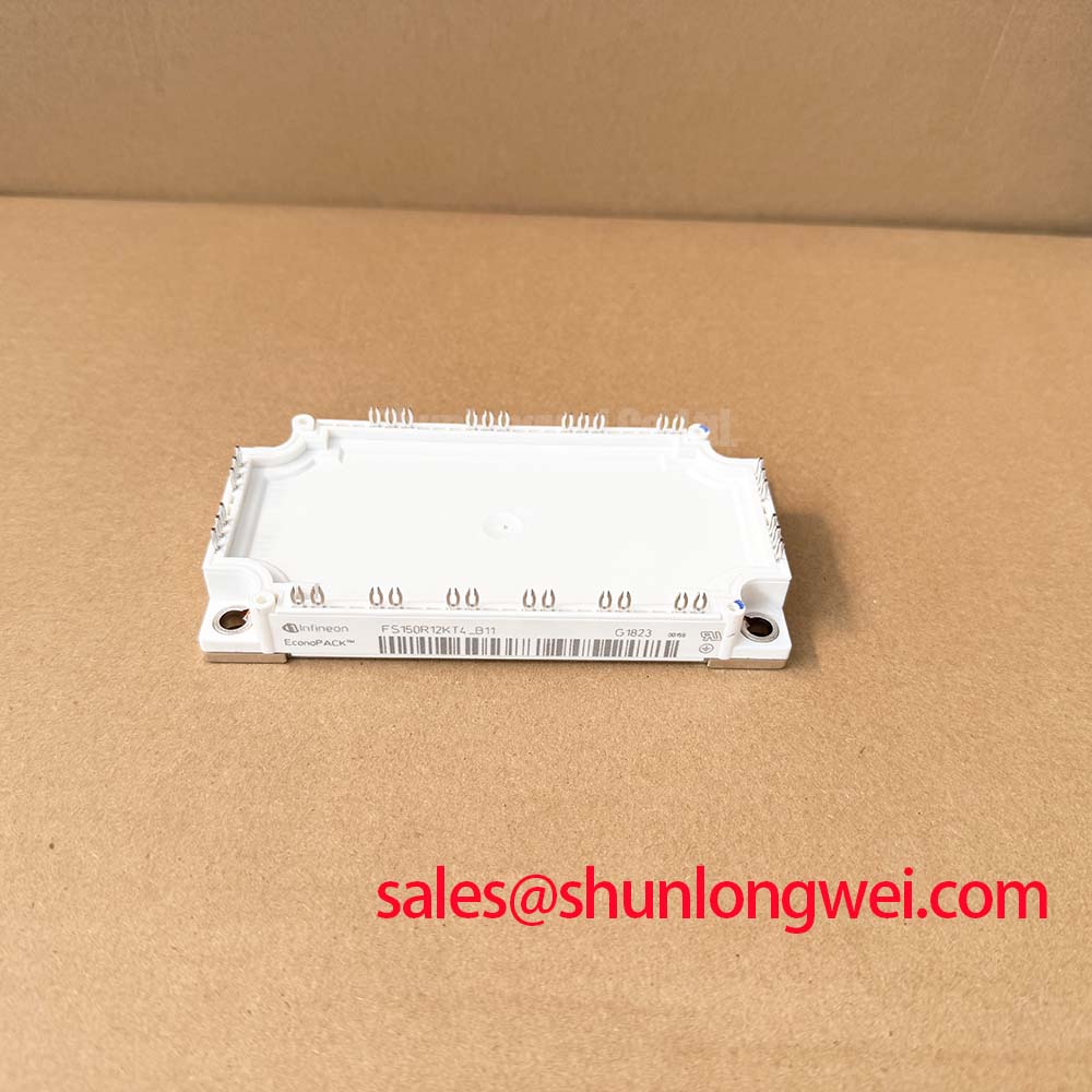
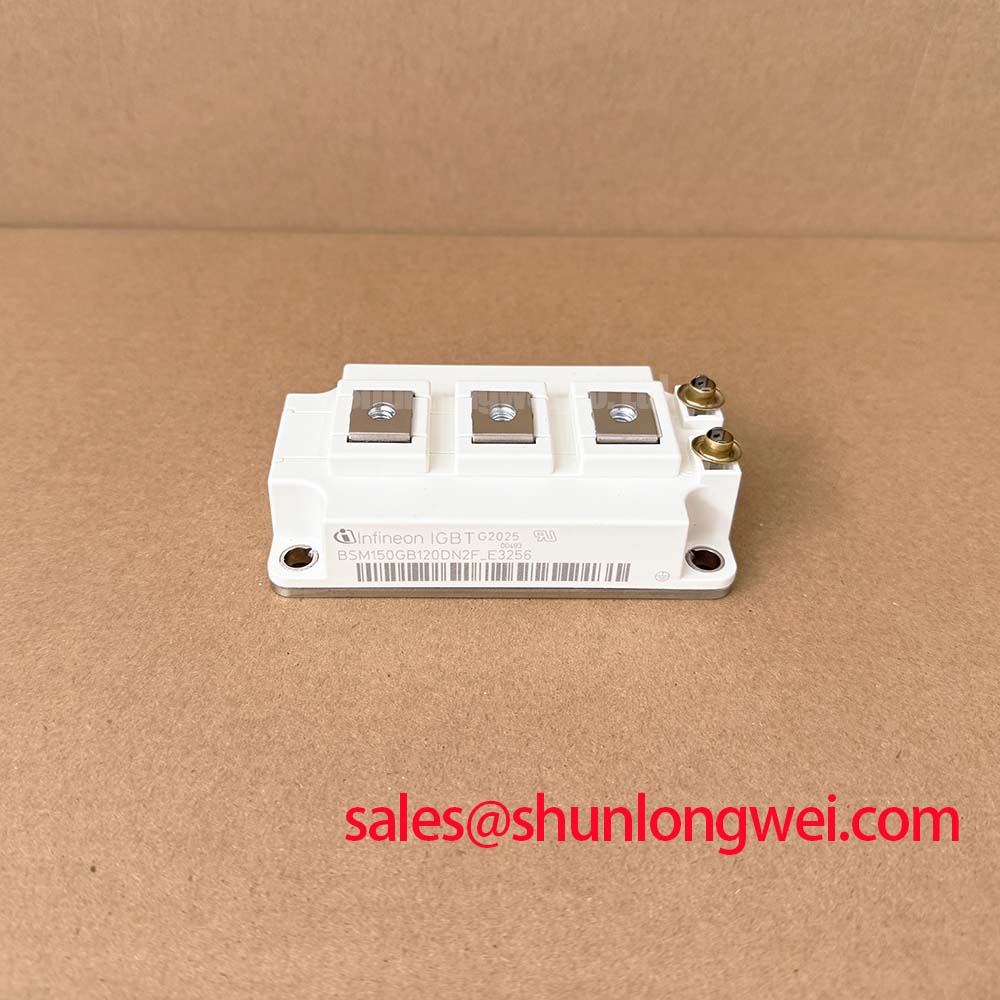
A cross-model comparison needs the same discipline. The SKM75GAL063D can be placed on a candidate review list, but its terminal arrangement, ratings, mounting interface, and switching characteristics must be checked independently; a related model name does not make it a drop-in replacement for the 1700 V, 200 A unit. In equipment that uses separate modules in adjacent conversion stages, the SKM75GB07E3 is likewise a distinct item for schematic-level comparison, not an assumed companion or interchangeable stage.
Preventing Spurious Faults: Thermal Stress Alleviation in Bidirectional Guidelines for SKM200GAL173D
In a utility-scale centralized battery energy storage PCS being assessed for compatibility, trace power flow through both charging and discharging modes before assigning a fault to the SKM200GAL173D. The bidirectional system may impose different current paths, switching patterns, and cooling demands in each mode. Whether this module is suitable for a particular position depends on the actual schematic, modulation method, thermal design, and verified device characteristics; the 200 A rating alone does not establish that suitability.
For an intermittent trip, preserve the controller fault record and compare it with DC-link voltage, measured branch current, gate-drive status, and available temperature measurements at the same operating point. A trip during a rapid power reversal may involve protection timing, sensing, cooling, or switching behavior. Repeat a controlled test only within the equipment’s approved procedure, and look for correlations rather than assigning a cause from the fault code alone.
Cyclic loading makes temperature history useful. As a Design Consideration, repeated rises and falls in junction temperature can affect module stress, but no lifetime or permitted number of cycles can be inferred from the three confirmed specifications on this page. Review the full manufacturer thermal and transient data before evaluating peak-shaving duty. If an overload has occurred, do not invent a fixed junction-temperature recovery window: wait for the equipment’s documented safe state, review the recorded event, and confirm the applicable protection and thermal limits before returning it to service.
Reliability discussions should remain tied to what can be measured on this installation. Compare cooling-path condition, mounting contact, and operating waveforms with the equipment’s established baseline. The Wide Bandgap Revolution guide offers background for technology-level comparisons, but it does not supply an operating-life claim for this IGBT module. Manufacturer-level module information is available through the Semikron-Danfoss power electronics hub; use the applicable part documentation for model-specific limits.
Assembly Integrity & Layout Architecture: Implementing Negative Gate Bias vs Active Miller Clamping for SKM200GAL173D
Inspect the gate-return path before changing drive settings to address an unexplained turn-on event. During a fast transition elsewhere in the converter, capacitive coupling through the device’s gate-to-collector path can disturb the off-state gate voltage. A long or shared return path can complicate that behavior. As a Design Consideration, keep the drive loop low in impedance and evaluate the gate voltage at the module terminals during the transitions most likely to produce a disturbance.
Negative off-state gate bias and an active Miller clamp are drive-circuit strategies, not confirmed built-in features of the SKM200GAL173D. Either approach requires compatibility checks against the exact device gate limits and the installed driver. A clamp is useful only when its connection and operating timing provide an effective discharge path; negative bias must likewise be assessed with the driver’s behavior during startup, shutdown, and faults. No bias value or clamp threshold should be selected from the module’s voltage and current ratings alone.
When investigating possible cross-conduction, capture both gate waveforms and the corresponding switching-node behavior with probes appropriate to the circuit. Compare the event with a known-good operating capture, and check whether ringing, return-path impedance, or driver timing changes coincide with the disturbance. If a damping change is considered, verify its effects on turn-on, turn-off, and measured voltage overshoot across the equipment’s required operating range.
Bench Tip: Keep the module and gate driver unpowered during cold-state diode checks, and protect gate terminals from electrostatic discharge while reconnecting probes.
Close the installation review by checking that the mounted busbars do not impose mechanical strain, that insulation distances remain appropriate after assembly, and that the final gate-drive measurements were taken with the production layout. Record the terminal map, cold-state readings, mounting observations, and waveform captures together so the next repair engineer can compare like conditions rather than relying on an isolated meter value.