


Content last revised on September 10, 2026
DC-Bus Operating Voltage Headroom Derating for Single Event Burnout (SEB) Immunity
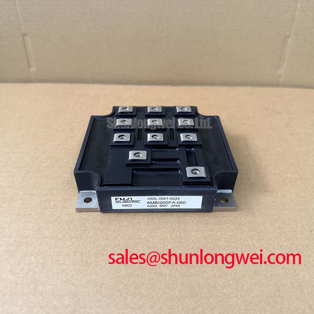
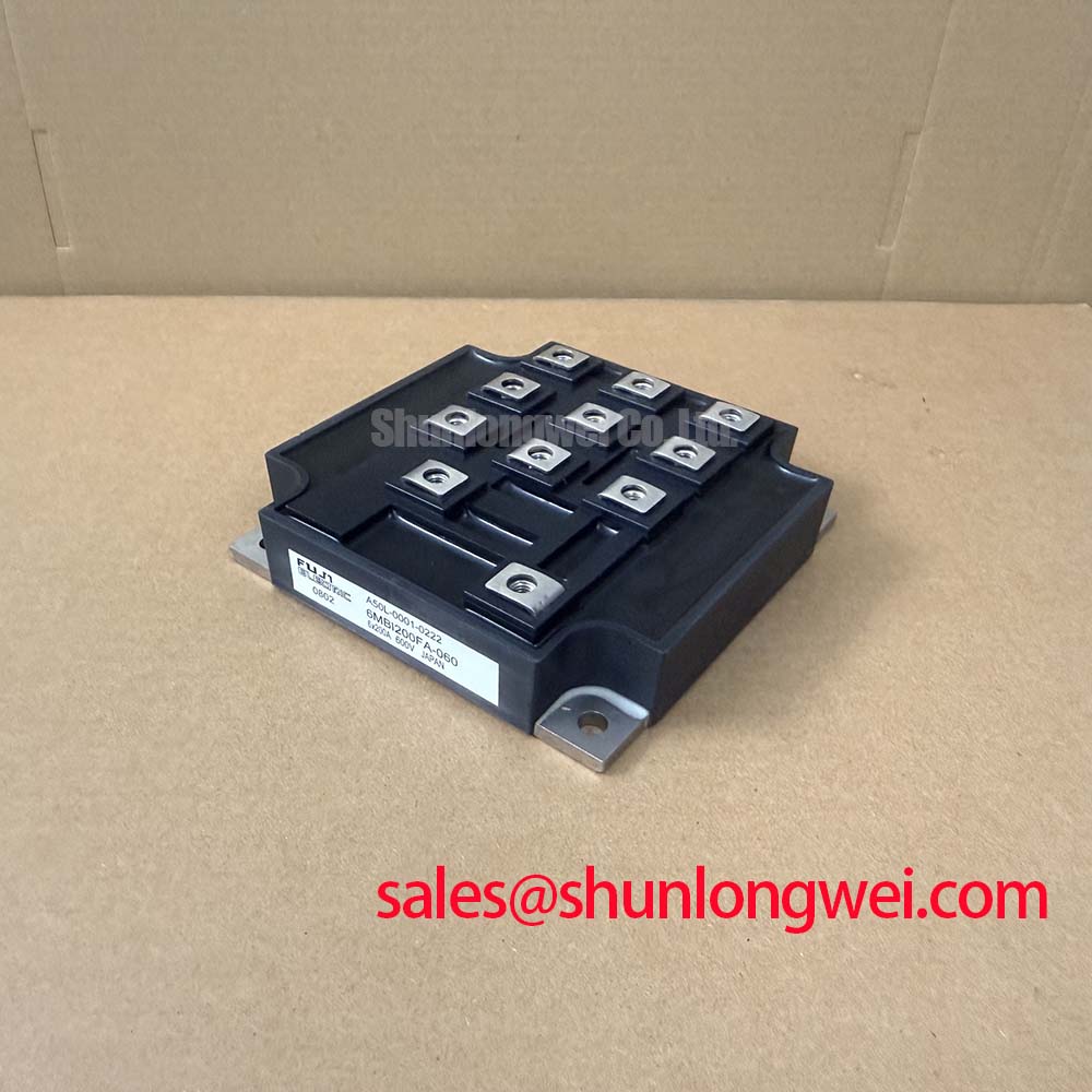
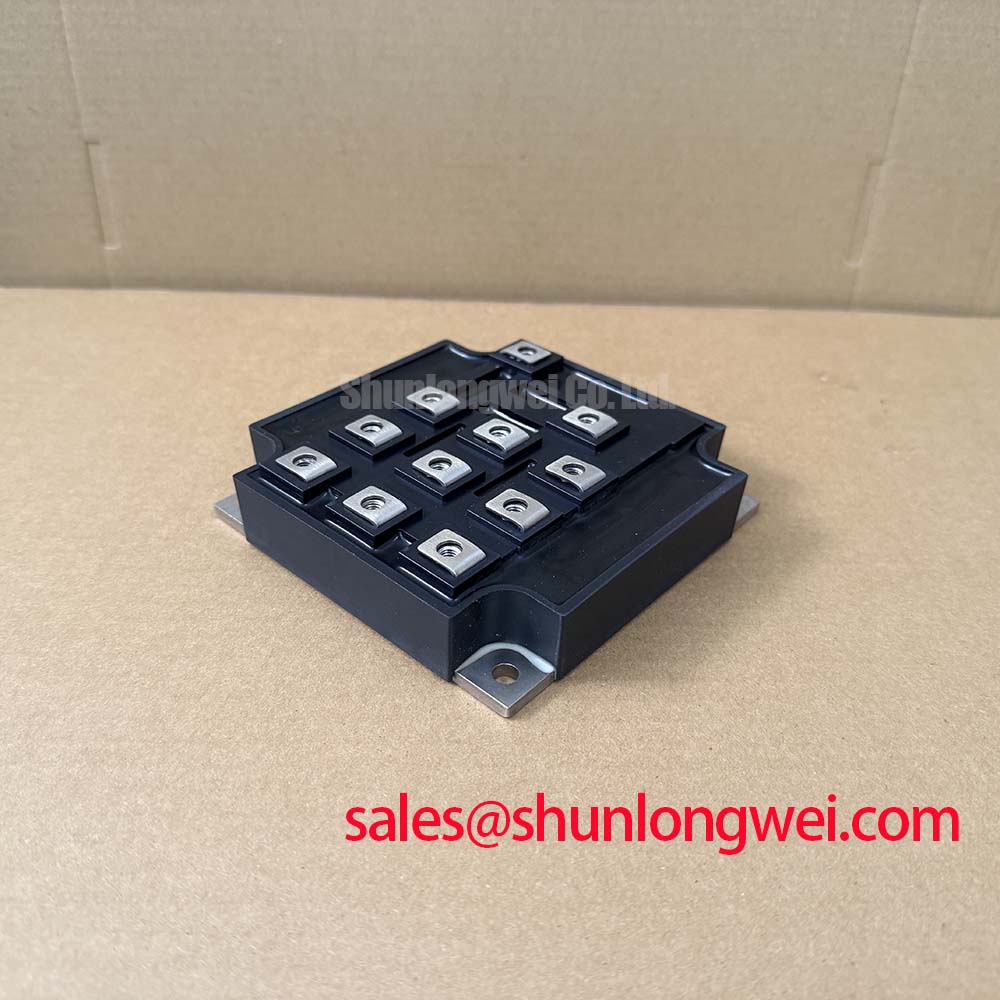
Incoming quality verification of high-power modules like the 6MBI200FA-060 begins on the static test bench, where we subject every terminal pair to rigorous leakage current and blocking voltage screening. The Fuji Electric 6MBI200FA-060 provides an integrated six-pack (three-phase inverter bridge) topology with a rated collector-emitter voltage of VCES = 600V (Official Datasheet Specification) and a continuous collector current rating of IC = 200A (Official Datasheet Specification) at allowable maximum junction temperatures up to Tj = +150°C (Official Datasheet Specification). In Commercial & Industrial (C&I) Battery Energy Storage System (BESS) Power Conversion Systems (PCS), the DC-link bus operates across fluctuating battery pack terminal voltages, subjecting the silicon die to continuous electric field stress.
When deploying battery storage converters at high altitudes exceeding 2000 meters above sea level, atmospheric terrestrial neutron flux increases significantly compared to sea-level installations. High-energy atmospheric neutrons colliding with the high-voltage depletion region of the reverse-biased N-drift layer can trigger localized avalanche multiplication, leading to Single Event Burnout (SEB). Because SEB represents a stochastic catastrophic failure mode rather than a wear-out mechanism, robust PCS engineering mandates setting a conservative steady-state DC operating voltage. Running the DC bus at 360V to 400V provides an adequate derating headroom under a 600V ceiling (Typical Starting Point for bench tuning), maintaining low failure-in-time (FIT) susceptibility across multi-megawatt containerized battery installations.
| Parameter | Symbol | Rated Value / Test Condition | Data Identity |
|---|---|---|---|
| Collector-Emitter Breakdown Voltage | VCES | 600 V | Official Datasheet Specification |
| Continuous Collector Current | IC | 200 A (TC = 25°C / 80°C) | Official Datasheet Specification |
| Repetitive Peak Collector Current | ICRM | 400 A (1 ms pulse) | Official Datasheet Specification |
| Max Power Dissipation (Per Device) | PC | 600 W (TC = 25°C) | Official Datasheet Specification |
| Gate-Emitter Voltage Rating | VGES | ±20 V | Official Datasheet Specification |
| Operating Junction Temperature | Tj | -40 to +150 °C | Official Datasheet Specification |
Incoming bench screening protocols require verifying the collector cutoff leakage current (ICES) using a curve tracer or high-voltage source measure unit (SMU). With the gate and emitter terminals shorted (VGE = 0V), apply 600V across the collector-emitter terminals and measure the leakage current, which should remain well within microampere thresholds at room temperature. Testing creepage and clearance distances across the power terminal pins against IEC 60664-1 pollution degree 2 standards guarantees that the physical package insulation will withstand transient overvoltages during utility-interactive PCS operations.
Evaluating Thermal Capacitance vs Heat Sink Time Constant under Surge Bursts
In commercial BESS PCS applications, rapid grid frequency response and sub-second peak-shaving events generate severe transient power losses. During these sudden load steps, the internal junction temperature (Tj) of the 6MBI200FA-060 rises much faster than the bulk temperature of the liquid cold plate or extruded aluminum heat sink. The silicon die and internal direct bonded copper (DBC) ceramic substrate govern the thermal capacitance for short pulses under 10 milliseconds, whereas the module's copper baseplate and external heat sink govern steady-state dissipation over seconds and minutes.
When handling transient grid faults where phase current surges toward the repetitive peak collector current limit of ICRM = 400A (Official Datasheet Specification), transient thermal impedance curves must be evaluated to ensure junction temperatures remain below the absolute ceiling of +150°C. For applications prioritizing modular single-switch topologies rather than integrated six-pack modules, engineers often compare these thermal response profiles against discrete building blocks like the 1MBI200NH-060 to achieve independent thermal spreading across isolated heatsink zones.
To prevent catastrophic inductive overvoltage during high-current switching transitions, minimizing the parasitic loop inductance of the DC busbar connection is critical. When 200A is interrupted during normal pulse-width modulation, high di/dt rates interact with parasitic busbar inductance, inducing peak collector-emitter spikes that can easily exceed the 600V silicon breakdown barrier. Engineers must design laminated planar busbars targeting a loop inductance of 25nH or less (Design Consideration), placing low-inductance polypropylene snubber film capacitors directly across the DC positive and negative input terminals of the module.
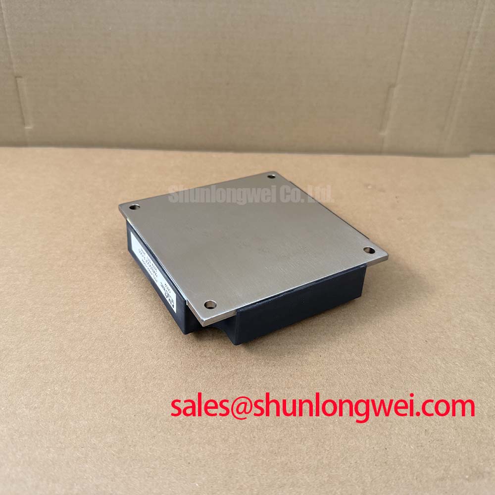
Modern silicon advancements, such as those found in the Fuji Electric 7th-Gen X-Series IGBT Modules, leverage thinner drift layers to reduce thermal impedance; however, maintaining structural integrity on mature modules requires precise mounting torque. When securing the module baseplate to a pre-machined heat sink exhibiting a flatness tolerance of less than 50 µm over 100 mm, torque the M5 mounting bolts in an alternating diagonal cross-pattern to 2.5–3.5 N·m (General Industry Design Consideration for M5). Apply a uniform 100 µm layer of high-conductivity thermal paste using a screen-printing stencil to eliminate microscopic air voids without causing hydraulic lift.
Desaturation (V_CE(sat)) Detection & Two-Stage Soft Turn-Off Short-Circuit Protection
Short-circuit withstand capability is paramount in energy storage converters due to the low source impedance of massive battery banks. The 6MBI200FA-060 provides robust short-circuit safe operating area (SCSOA) characteristics, allowing a short-circuit duration up to 10 µs under specified gate drive conditions. Gate driver boards designed for this module must incorporate high-speed desaturation detection circuits that monitor the forward voltage drop across the collector-emitter terminals during the on-state.
Under a dead-short condition (Type-I or Type-II fault), the IGBT leaves the deep saturation region and enters active desaturation, causing VCE to climb rapidly toward the DC bus voltage while conducting fault currents several times higher than the rated 200A. If the gate driver attempts an instantaneous hard turn-off at such extreme current levels, the massive di/dt through parasitic stray inductance will destroy the device via overvoltage punch-through. Implementing a Two-Stage Soft Turn-Off (2SSTO) circuit clamps the gate discharge curve, slowly ramping gate-emitter voltage down over 2 to 4 µs to safely extinguish the fault current within SCSOA boundary limits.
💡 Bench Tip: Before mounting replacement modules into a power rack, always perform a static diode-check and gate-threshold screening. Use an electrostatic discharge (ESD) grounded wrist strap. Measure the cold-state forward voltage drop (VF) of the integrated free-wheeling diodes across all six branches using a digital multimeter on diode mode; standard silicon junctions should read between 0.35V and 0.55V at room temperature. Check gate-to-emitter impedance with an insulation tester at 20V: any leakage resistance below 10 MΩ indicates dielectric oxide rupture across the gate barrier.
Comprehensive failure analysis, gate drive damping techniques, and curve tracer screening workflows are thoroughly cataloged in the Field Engineer’s Handbook for technicians conducting bench-level diagnosis. When tuning gate driver circuitry, select external gate resistors (RG) starting around 10 Ω (Typical Starting Point for bench tuning) to balance switching losses against electromagnetic interference (EMI), while ensuring the bipolar gate driver delivers clean +15V on-state turn-on and -5V to -15V active reverse-bias turn-off for guaranteed dv/dt noise immunity.
Managing High-C-Rate Battery Cycling Swings via Symmetrical DC-DC Switching
Bi-directional C&I battery storage converters execute continuous four-quadrant active and reactive power flow, alternating between charge (buck mode) and discharge (boost mode) regimes. During high C-rate cycling (such as 1C to 2C fast-ramping events during dynamic peak shaving), the internal power chips undergo continuous power cycling (ΔTj) swings. This repetitive thermal expansion mismatch between the silicon die, solder layers, and the copper baseplate generates mechanical shear stress on the aluminum bond wire stitch bonds.
To maximize service life across decades of field cycling, the symmetrical three-phase bridge of the 6MBI200FA-060 must be driven with balanced PWM modulation patterns that evenly distribute conduction losses and reverse-recovery diode dissipation across all six internal switches. Dynamic brake chopper sub-circuits or auxiliary power topologies often operate alongside the main bridge to absorb dynamic DC bus overvoltages; for dedicated braking functions, engineers reference specialized hardware such as Fuji Electric Brake Chopper IGBT Modules to decouple chopper energy management from the main three-phase bridge.
In multi-stage storage architectures, lower-power auxiliary stages frequently handle pre-charge, active DC clamping, or control power generation. Auxiliary modules such as the 6MBI10S-120 often serve these auxiliary power roles within the same enclosure, maintaining consistent gate-drive topology and control hardware across the converter cabinet.
⚠️ Field Alert: When retrofitting or servicing high-power PCS enclosures, never reuse deformed spring washers or uncalibrated mounting hardware. Verify that laminated DC busbars do not exert permanent mechanical shearing or bending forces on the module's main power terminals. Uneven physical torque on power lugs can crack the internal substrate ceramic, causing immediate dielectric breakdown during high-voltage DC-link energization.