


Content last revised on June 12, 2026
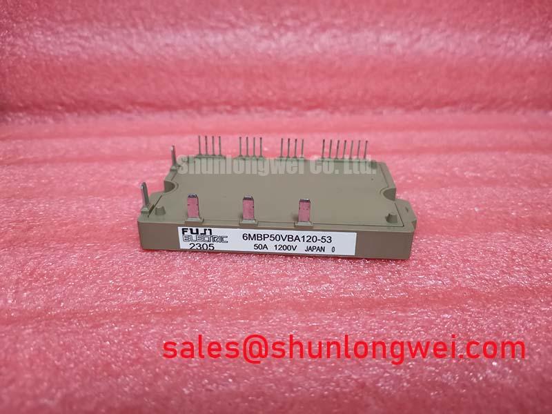
6MBP50VBA120-53 | 1200V 50A CIB IGBT Module for Motor Drives
An Engineering-Centric Overview
A highly integrated 1200V CIB module delivering exceptional efficiency and design simplicity for compact motor control systems. The Fuji Electric 6MBP50VBA120-53 integrates a full power conversion stage into a single, thermally efficient package. Key specifications include: 1200V | 50A (Inverter) | VCE(sat) 1.9V (typ). This integration delivers two critical engineering benefits: significantly reduced conduction losses and radically simplified system assembly. By combining the converter, inverter, and brake circuits, it directly answers the engineering challenge of designing more compact and reliable power stages without sacrificing performance. For motor drives up to approximately 15 kW requiring a compact, all-in-one power stage, the 6MBP50VBA120-53 offers an optimal balance of integration and performance.
Key Parameter Overview
Analyzing the Specs for Integrated Drive Design
The technical specifications of the 6MBP50VBA120-53 are structured to support all three internal power functions. The low saturation voltage of the inverter stage is a defining characteristic, directly contributing to lower heat dissipation and higher system efficiency. The parameters are organized by their function within the module to facilitate a clear evaluation for your specific application.
| Inverter Section (per IGBT) | ||
|---|---|---|
| Parameter | Value | Conditions |
| Collector-Emitter Voltage (Vces) | 1200V | |
| Continuous Collector Current (Ic) | 50A | Tc = 80°C |
| Collector-Emitter Saturation Voltage (VCE(sat)) | 1.9V (typ), 2.4V (max) | Ic = 50A, VGE = 15V |
| Thermal Resistance (Rth(j-c)) | 0.43 °C/W | Per IGBT |
| Brake Section (per IGBT) | ||
| Collector-Emitter Voltage (Vces) | 1200V | |
| Continuous Collector Current (Ic) | 25A | Tc = 80°C |
| Collector-Emitter Saturation Voltage (VCE(sat)) | 2.0V (typ), 2.5V (max) | Ic = 25A, VGE = 15V |
| Converter Section (per Diode) | ||
| Repetitive Peak Reverse Voltage (VRRM) | 1200V | |
| Forward Current (IF(AV)) | 50A | |
This table represents a selection of key parameters. For comprehensive electrical and thermal characteristics, please refer to the official documentation.
Download the 6MBP50VBA120-53 datasheet for detailed specifications and performance curves.
Application Scenarios & Value
Achieving Compact and Efficient AC Motor Control
The 6MBP50VBA120-53 is engineered for power conversion systems where space, efficiency, and reliability are primary design drivers. Its all-in-one CIB (Converter-Inverter-Brake) architecture makes it a cornerstone component for a wide range of industrial applications.
- Variable Frequency Drives (VFDs): In a typical Variable Frequency Drive (VFD) for industrial conveyors or HVAC fans, cabinet space is often limited. The high level of system integration within the 6MBP50VBA120-53 drastically reduces the PCB footprint and simplifies the bus bar structure compared to discrete solutions. This consolidation not only saves space but also reduces assembly time and potential wiring errors.
- Servo Drives: Precision motion control in robotics and CNC machinery demands efficient power stages to minimize heat buildup within the equipment. The low VCE(sat) of this module reduces conduction losses, a major source of waste heat. This thermal efficiency allows for more compact heatsink designs, contributing to a smaller, more reliable servo drive. What is the primary benefit of the 6MBP50VBA120-53's integrated design? It simplifies assembly and reduces system size.
- General Purpose Inverters: For applications like small industrial pumps and commercial machinery, the module's robust 1200V rating provides ample design margin for 380-480V AC line-operated systems, enhancing overall system ruggedness.
While the 50A rating of this module is ideal for many mid-power applications, systems requiring lower current may consider the related 6MBP25VAA120-50. Conversely, for more demanding AC motor control, the 7MBR75VB120-50 offers a higher current handling capability within a similar integrated framework.
Technical Deep Dive
Dissecting the CIB Topology for System-Level Advantages
The true value of an integrated module like the 6MBP50VBA120-53 extends beyond component consolidation. By placing the rectifier bridge, three-phase inverter, and brake chopper into a single, optimized package, Fuji Electric minimizes the internal stray inductance between these critical stages. Lower inductance reduces voltage overshoots and ringing during high-speed switching events, which in turn decreases stress on the IGBTs and diodes. How does the low VCE(sat) impact performance? It directly lowers conduction losses and improves efficiency.
Think of the power flow in a discrete component layout as navigating multiple side roads to get between destinations, creating opportunities for delays and conflicts. The integrated PIM is like a purpose-built expressway, providing a direct, low-resistance path that minimizes electrical "traffic jams" (voltage spikes). This inherent electrical efficiency can simplify or even eliminate the need for complex external snubber circuits, further reducing component count and saving valuable PCB real estate. This level of integration is a key factor in building robust and EMI-compliant drive systems.
Frequently Asked Questions (FAQ)
What is the primary engineering advantage of the integrated CIB (Converter-Inverter-Brake) topology in the 6MBP50VBA120-53?
The primary advantage is the simplification of the power stage design. By integrating all three core functions into one module, engineers can significantly reduce the physical footprint, minimize assembly complexity, and lower the stray inductance in the power circuit. This leads to a more compact, reliable, and cost-effective system, as it reduces the need for extensive bus bar design and multiple discrete components.
How does the built-in NTC thermistor improve the reliability of a motor drive system?
The NTC thermistor provides a direct, real-time measurement of the module's substrate temperature. This data can be fed back to the system's microcontroller to implement precise over-temperature protection. If the drive operates under overload conditions or with insufficient cooling, the controller can trigger an alarm, reduce the output power (derating), or initiate a safe shutdown before the IGBT junction temperature exceeds its maximum limit. This proactive thermal management is crucial for preventing catastrophic failures and extending the operational life of the drive, a key consideration covered when decoding the specs for long-term field performance.
For engineering teams evaluating this module, the next step involves cross-referencing these specifications with the specific load cycle and thermal constraints of your application. Our team is available to provide further clarification on the datasheet to support your design process.