

Content last revised on September 13, 2026
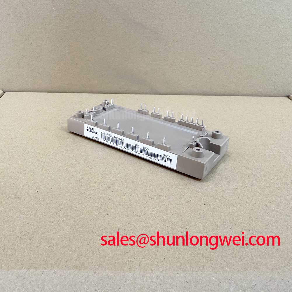
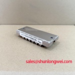
6MBR50UA060-50 Fuji Electric 600 V 50 A PIM IGBT Module
| Manufacturer | Fuji Electric |
| Part Number | 6MBR50UA060-50 |
| Product Category | IGBT Module |
| Collector Emitter Voltage | 600 V, Official Specification |
| Continuous Collector Current | 50 A, Official Specification |
| Configuration | PIM converter inverter brake, Official Specification |
| Mounting Type | Screw and baseplate, Official Specification |
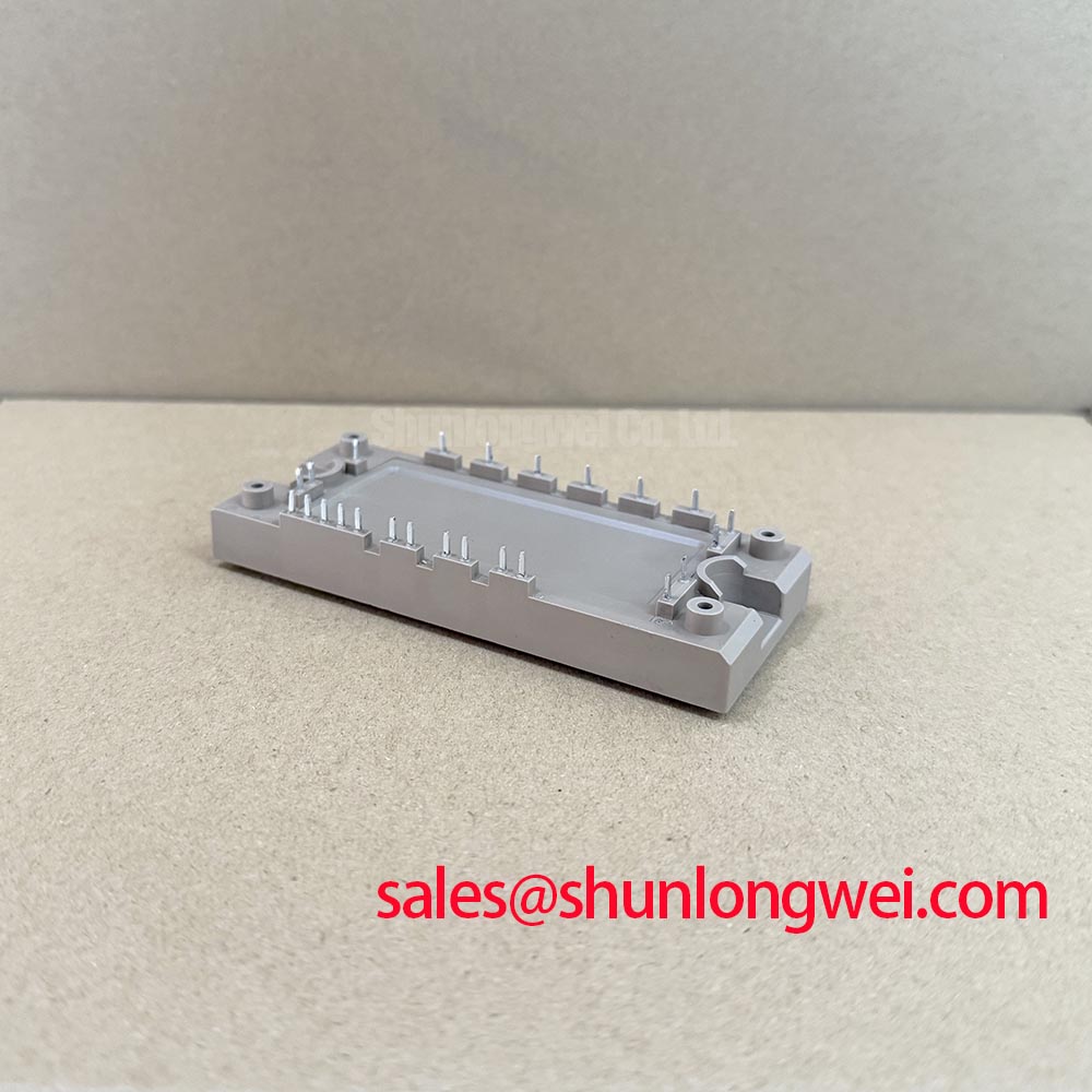
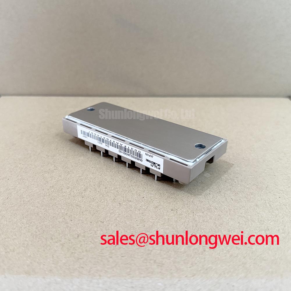
Before powering a replacement assembly, isolate the module, inspect the case and terminals, then compare cold state resistance and diode direction against a known good unit. The Fuji Electric 6MBR50UA060-50 is a 600 V, 50 A PIM IGBT module combining converter, inverter, and brake functions in one screw and baseplate package. Its published configuration can reduce the number of separate power semiconductor mounting points, while the baseplate supports a controlled thermal interface when the surrounding heatsink and clamping arrangement are suitable.
The voltage and current figures are official device specifications, not a complete system operating prescription. Actual switching frequency, duty cycle, overload duration, heatsink temperature, gate drive conditions, DC link level, and cooling performance must be checked at equipment level. Engineers evaluating a high dynamics multi axis CNC drive or robotics servo amplifier should confirm the original circuit topology, terminal assignment, protection logic, and mechanical envelope before installation.
Preventing Spurious Faults with Dynamic Gate Impedance Control
Fast collector voltage transitions can couple through the Miller capacitance and disturb a non conducting switch. A Design Consideration for this module is to keep the gate drive return path compact, separate high current commutation paths from control wiring, and use a clearly defined gate resistor location close to the module terminals. Active Miller clamp circuitry and negative gate bias may be evaluated as system level options where the isolated driver, insulation coordination, and gate voltage limits support them. These functions are not stated as factory features of the 6MBR50UA060-50.
For an incoming test, use the diode range only on terminals identified from the applicable Fuji Electric documentation and keep the module fully disconnected from the gate driver. A forward reading across an integrated freewheel diode can help confirm polarity, but a multimeter result is not an IGBT dynamic health test. If readings differ between corresponding paths, repeat the check with identical lead placement and compare the known good signal path before drawing a failure conclusion.
Optocouplers or digital isolators on an industrial drive board should be assessed for common mode transient immunity in the complete layout, not by assuming a value from the power module. The integrator should verify isolation clearance, gate driver supply sequencing, and interlock behavior during oscilloscope testing. Bench Tip: Use an ESD controlled bench and record the cold state baseline before applying any gate signal.
Transient Dynamics and Thermal Capacitance in Pulsed Operation
The PIM arrangement places converter, inverter, and brake functions within the same thermal installation, so the heatsink interface must be evaluated for the actual combined loss profile. A Design Consideration is to treat short overloads as transient thermal events rather than relying only on steady state current. The system model should combine junction to case data from the applicable datasheet with case to heatsink and heatsink to ambient measurements. Peak junction temperature is then checked against the manufacturer’s permitted operating boundary during the real pulse sequence.
Thermal capacitance can temporarily absorb a load step, but it cannot remove average heat from repeated CNC acceleration or regenerative braking cycles. Designers should verify baseplate flatness, interface material coverage, mounting pressure, airflow, and neighboring heat sources. External cooling concepts, including heat pipe systems, require mechanical and thermal validation; the general operating principle is described in Heat Pipe Phase Change Cooling in High Power Electronics.
Dead time and complementary gate interlock are controlled by the drive system. The correct buffer depends on driver propagation mismatch, turn off behavior, load current, temperature, and measured switching waveforms. During commissioning, verify that both command channels cannot be active together and inspect the gate emitter voltage directly at the module terminals rather than at the controller connector.
Operational Boundaries and Mismatched Parameter Limits
The stated 600 V collector emitter voltage and 50 A continuous collector current define important identity points for this product, but they do not authorize operation at those limits under every thermal or switching condition. The procurement engineer should compare the module’s official ratings with the drive’s DC link, motor current waveform, braking energy, ambient temperature, and fault response. Short circuit withstand, switching loss, insulation, and temperature limits must be taken from the relevant Fuji Electric documentation rather than inferred from the headline ratings.
When parallel current paths are considered at system level, similar electrical path resistance, symmetrical gate wiring, and matched commutation inductance are Design Considerations for dynamic balance. The positive temperature coefficient commonly associated with IGBT saturation voltage can assist static current sharing, but it does not remove switching imbalance caused by layout or driver mismatch. Verify current distribution with temperature and waveform measurements before approving a parallel arrangement.
For a potential replacement review, compare terminal geometry, mounting pattern, thermal contact area, brake circuit requirements, and controller protection thresholds. The 7MBR50LC060 may be examined as a separate, documented device during a neutral compatibility study; it should not be treated as an automatic substitute without electrical and mechanical verification. Broader gate drive, thermal, and topology considerations are available in the IGBT Design and Integration guide.
Benchtop Waveform Tuning for Hard Switching Transients
Start waveform validation at reduced system energy and monitor gate emitter voltage, collector emitter voltage, phase current, and DC link behavior with suitably rated probes. A hard switching overshoot may involve stray inductance, gate loop impedance, diode recovery, commutation timing, or probe technique. The corrective process should therefore change one controlled variable at a time while checking peak voltage against the module’s official boundary.
Bootstrap gate supplies deserve specific attention in half bridge drive circuits. The capacitor must retain adequate voltage during the intended high side on time and recharge correctly during the available low side interval. Designers should verify capacitor ripple current, leakage, driver consumption, charging path impedance, and diode reverse recovery under the actual switching pattern. The bootstrap network is part of the gate drive system and is not an integrated specification of this Fuji Electric module.
Short circuit protection should be coordinated with the driver and control system. Type I or Type II detection concepts, desaturation sensing, blanking behavior, and soft turn off are system design matters; any claimed sub 10 microsecond response must be confirmed from the selected protection circuit and its test evidence. A two stage turn off approach may reduce induced voltage stress by limiting the rate of current collapse, but the final gate profile must be tuned on the bench with the actual bus layout and load.
If a protection trip occurs, preserve the event record before replacing the module. Check gate commands, isolated supply stability, phase wiring, brake path continuity, DC link discharge behavior, and the oscilloscope probe reference. This sequence helps distinguish a module fault from a driver, interlock, commutation, or measurement problem without assigning a single cause prematurely.