


Content last revised on September 30, 2026
7MBP100KB060 Thermal Electrical Optimization for Isolated DC DC Power Supply Sizing
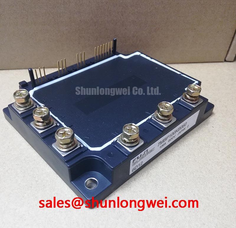
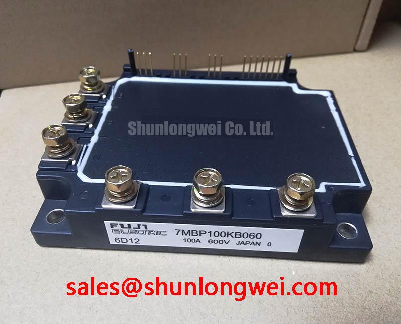
| Product | 7MBP100KB060 |
|---|---|
| Manufacturer | Fuji Electric |
| Product category | Power Integrated Module |
| Rated voltage | 600.0 V |
| Rated current | 100.0 A |
| Package | Fuji Power Module |
Measure the gate drive supply at the module terminals with the traction inverter disabled, then compare the measured voltage and return path against the original drive documentation before energizing the power stage. The 7MBP100KB060 is a Fuji Electric power module rated at 600.0 V and 100.0 A; those are official product specifications, not a complete system design limit.
For an electric forklift or warehouse traction controller, inspect the isolated gate supply transformer, rectifier, regulator, and return conductors as one switching loop. A gate supply that appears correct at the isolated converter can show disturbances at the module pins when collector current changes quickly. Use a differential probe at the actual gate and emitter reference points, and compare the result with a known good phase. Ringing that is absent at the supply board but present at the module usually warrants an inspection of the gate loop, connector contacts, grounding arrangement, and probe technique.
Reinforced galvanic isolation and common mode transient immunity are system requirements that must be verified from the selected isolated power supply documentation. The supplied product information does not establish a guaranteed isolation rating above 5 kV or a CMTI rating above 100 kV per microsecond for this specific module. Designers should select the isolation barrier according to the DC link, pollution environment, creepage path, transient test conditions, and applicable equipment standard. The isolated converter, gate driver, module, and control board must be assessed as a complete interface.
Keep the power switching loop physically separate from low level feedback and communication wiring. Minimize parasitic inductance in the gate drive path, provide a controlled return route, and avoid sharing a high current emitter or power return conductor with sensitive control references unless the gate driver architecture explicitly allows it. When common mode ground movement is suspected, measure the control reference, isolated supply reference, and module emitter reference simultaneously. A difference between these waveforms can indicate layout coupling or return path impedance rather than an immediate module defect.
Negative gate turn off bias is an application choice, not an official rating supplied for this part. Some inverter architectures use it to improve noise immunity, while others use a controlled positive gate drive and active clamping arrangement. The correct value, timing, and protection method depend on the gate driver, switching speed, short circuit behavior, and manufacturer data for the complete module. The system engineer should validate turn on and turn off thresholds during double pulse and fault testing rather than adopting a fixed bias value from a general application example.
For the input and protection network, evaluate the DC link capacitor, fuse, contactor, braking path, and MOV coordination together. A MOV can help absorb defined transient energy, but it does not replace correct commutation layout, snubber selection, or DC link voltage control. Check the MOV operating voltage, clamping behavior, pulse energy, thermal clearance, and failure containment against the actual battery and charger conditions. In bidirectional battery traction systems, repeated charge and discharge transitions can alter thermal cycling and transient duty, so switching waveforms should be captured in both power flow directions.
The Fuji Electric power semiconductor and IPM module resources provide useful background for evaluating module interfaces and protection concepts. The Fuji Electric PIM 7 pack information can also help engineers distinguish an integrated module topology from a discrete switching assembly. These references should be read alongside the original equipment schematic and the exact gate driver documentation.
Preventing Spurious Faults During High Altitude Operation
Capture the collector emitter waveform at the module terminals during the highest observed battery voltage and the fastest commanded turn off, then compare the peak with the specified blocking voltage. This measurement is more useful in field troubleshooting than assigning a universal cosmic ray FIT value to the 7MBP100KB060 without an authoritative Fuji Electric reliability source.
Single event burnout, terrestrial neutron exposure, and altitude related reliability require application specific evidence. No FIT rate, neutron flux value, or guaranteed high altitude derating factor is established in the supplied product data. Treat operation above 2000 m as a design consideration requiring review of the applicable equipment standard, DC link operating range, switching stress, enclosure environment, cooling performance, and available semiconductor reliability data. Do not convert a general altitude rule into a claimed failure probability for this module.
Maintain voltage headroom by testing the actual maximum DC link voltage, overshoot, ringing, and repetitive transient pattern. The usable margin is determined by the complete commutation network and the rated blocking voltage, not by nominal battery voltage alone. If the oscilloscope shows a narrow overshoot near the voltage boundary, investigate bus bar inductance, capacitor placement, gate resistance, freewheel path behavior, snubber layout, and measurement loop area before changing the module.
Terminal creepage and electrical clearance should be checked against the working voltage, transient category, pollution level, insulation material group, altitude correction, and enclosure construction. The 600.0 V rating identifies the module voltage class, but it does not by itself define the required external spacing of the inverter assembly. When the module is installed in a forklift traction controller, inspect contamination, condensation, conductive dust, and cable routing around the power terminals. The final spacing decision belongs to the system insulation design and its compliance assessment.
Thermal interface material is also part of the electrical stress picture because poor heat transfer can raise junction temperature and alter switching behavior. A specified 50 to 80 micrometre layer, a particular baseplate flatness, or a fixed screw torque value must not be attributed to this model without the Fuji Electric mechanical drawing or assembly instruction. Use the material supplier data and the module manufacturer’s mounting documentation to determine application thickness, spread pattern, surface preparation, and fastener procedure.
Field Alert: Isolate the battery and DC link, confirm the discharge state with an approved meter, and keep the module disconnected from the gate driver while checking terminal resistance or mechanical fit.
For technical background on switching efficiency and power device behavior, engineers can review the industrial drive efficiency guide. It is a technical reference rather than a substitute for the Fuji Electric specification applicable to this module.
Field Diagnostics and Commissioning with Baseplate Thermal Grease Control
Inspect the mounting surface, baseplate contact pattern, fastener seating, and thermal compound distribution before applying switching power to a replacement 7MBP100KB060. Look for trapped debris, uneven compound transfer, visible rocking, damaged threads, and distortion around the mounting points. These checks can reveal a thermal installation problem even when a cold electrical resistance test appears normal.
Thermal grease should fill microscopic surface irregularities without creating a thick compliant layer that reduces heat transfer. The correct application thickness is determined by the compound, baseplate geometry, heatsink finish, clamping method, and manufacturer instructions. The supplied factory data confirms the Fuji Power Module package but does not specify a universal 50 to 100 micrometre TIM thickness for every heatsink arrangement.
Clean both mating surfaces with a process approved for the thermal compound and avoid touching the prepared surfaces with bare fingers. Check the heatsink for burrs, local high spots, and curvature before positioning the module. If the baseplate does not sit naturally on the heatsink, do not use fastener pressure to force alignment. Correct the mechanical interface first, because excessive local pressure can distort the baseplate or leave other areas with inadequate contact.
Use a cross pattern and staged tightening only when it is consistent with the module drawing and fastener specification. The correct torque is system determined by the screw size, washer arrangement, thread condition, heatsink material, and Fuji Electric assembly instructions. Record the actual procedure used during service so a later thermal fault can be compared with the original installation rather than relying on visual inspection alone.
After commissioning, monitor case temperature, phase current balance, switching waveform symmetry, and thermal rise under a controlled load. A temperature difference between phases may result from current imbalance, sensor placement, airflow, gate timing, cable impedance, or thermal contact. Treat it as a diagnostic observation and verify each path with comparative measurements rather than assigning the condition to the module without evidence.
For replacement planning, the 7MBP100RA060-05 may be evaluated as a related Fuji Electric module when its electrical topology, mechanical outline, terminal arrangement, gate requirements, protection behavior, and equipment documentation are confirmed. Similar voltage and current labels do not establish drop in compatibility. The inverter schematic and original module drawing remain the controlling references.
Output Sinusoidal Filter and dv dt Reactor Evaluation
Probe the motor terminals and inverter output terminals at the same operating condition, then compare the rise time, ringing, and peak voltage with the cable connected and disconnected where the test procedure permits. A long motor lead can interact with cable impedance and motor input impedance, producing reflected wave behavior and terminal stress; an observed peak approaching twice the local DC bus level is a system measurement that requires verification, not a fixed characteristic of the 7MBP100KB060.
A sinusoidal filter and a dv per dt reactor solve different problems. A sinusoidal filter is intended to reshape the inverter output toward a motor friendly waveform, while a reactor limits the rate of voltage change and can reduce high frequency stress without producing the same output waveform. Selection depends on motor insulation, cable length, switching frequency, carrier pattern, leakage current, acoustic behavior, thermal loss, and the drive manufacturer’s limits.
When a traction inverter is used with an electric forklift motor, check whether the motor controller expects a raw PWM waveform, a reactor protected output, or a filtered sinusoidal supply. A filter that is suitable for a fixed speed industrial motor may interfere with current control, regenerative operation, braking response, or sensor feedback in a battery traction system. Designers should verify resonance behavior, damping, filter current rating, and bidirectional energy flow during acceleration and regeneration.
Keep the output filter connection short, compact, and separated from control wiring. Minimize the physical loop formed by the switching terminals, filter components, and motor return path to reduce unwanted coupling. During troubleshooting, inspect cable shield termination, motor frame bonding, encoder wiring, and common mode current paths. A waveform change after reconnecting the motor cable may indicate impedance interaction, measurement reference error, or grounding coupling, so compare differential and common mode measurements before modifying gate timing.
The 7MBR100SB060 can be considered as a related module in an evaluation of the complete power topology. Its presence does not define compatibility with the 7MBP100KB060, and the rectifier, DC link, braking circuit, gate driver, and output network must be checked against the original equipment design.
During final commissioning, sweep the operating points that matter to the equipment: low speed torque production, rated traction demand, regenerative braking, battery voltage extremes, and thermal steady state. Confirm that collector emitter overshoot, gate waveform integrity, motor terminal voltage, filter temperature, and protection trips remain within the documented system limits. The 600.0 V and 100.0 A official ratings identify the product’s principal electrical class, while safe operation depends on the verified inverter topology, cooling assembly, insulation system, and switching conditions.