Content last revised on October 14, 2026
7MBP150RA120-14 Thermal-Electrical Optimization: Dynamic Braking Chopper Operation Practical Tuning
With the DC link discharged and the module disconnected from the drive board, match the terminal markings on 7MBP150RA120-14 to the equipment schematic before placing a meter across the power terminals. Record diode-mode readings in both polarities along each documented freewheeling path, using consistent lead orientation and temperature. Compare equivalent branches rather than treating a single forward-voltage reading as a pass certificate; connected resistors, capacitors, and control circuitry can otherwise obscure the measurement.
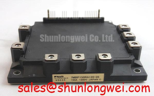
The Fuji Electric 7MBP150RA120-14 is an intelligent power module with a 1200 V voltage rating and a 150 A current rating under the manufacturer's specified conditions. For incoming inspection, keep the terminal drawing, electrical test conditions, and mounting instructions with the acceptance record. An insulation assessment also needs the manufacturer's specified test connections and procedure: the semiconductor voltage rating is not an instruction to apply that voltage between every terminal and the mounting surface.
💡 Bench Tip: Use ESD precautions and compare cold-state readings with a documented known-good module before reconnecting the control board.
Trace the braking-current path from the DC-link terminals to the chopper switch and resistor before evaluating a deceleration overvoltage complaint. As a Design Consideration, the equipment schematic must establish whether braking occurs through a module-associated circuit or a separate switching stage. Do not assign a braking terminal from the model name alone. Check resistor continuity, connector condition, and the commanded braking signal with the power stage isolated before proceeding to energized measurements.
During deceleration, regenerated energy raises the DC-link voltage unless the system returns it to the supply or dissipates it through a braking circuit. Resistor evaluation therefore starts with the actual load, stopping profile, repetition rate, and resistor assembly's documented pulse capability. A resistor that passes a cold resistance check can still have an unsuitable energy rating or an intermittent connection under thermal expansion. Compare resistance and temperature behavior with the equipment specification rather than choosing a resistor solely from the module's current rating.
For controlled switching tests, capture DC-link voltage, braking command, and switch voltage on the same time base using suitably rated measurement equipment. A rising bus with no braking command points toward a different investigation than a valid command followed by ineffective current flow. Overshoot at turn-off warrants examination of the commutation loop, connection geometry, and damping arrangement. Keep outgoing and return current paths close where insulation requirements permit, and evaluate peak voltage at the device terminals rather than only at a distant bus capacitor.
Clearance around resistor terminals and power conductors should follow the equipment's insulation coordination, working voltage, contamination conditions, and enclosure requirements. Routing a control harness alongside the braking loop can couple switching disturbances into command or fault signals. Where the drive uses an optocoupler or digital isolator, compare its common-mode transient immunity with the measured disturbance and inspect the local supply return. This is a system-level compatibility check, not an EMC certification claim for the module.
When reviewing the surrounding supply and converter topology, 7MBR35SD120 provides a related product reference for comparison; its circuit diagram must establish its role before it is considered for a rectifier or complementary stage. Fuji Electric's PIM 7-Pack information is useful for understanding that product family, but family-level terminology does not establish identical connections or functions for 7MBP150RA120-14.
7MBP150RA120-14 Circuit Protection & Reliability: Baseplate Profile and Mounting Screw Tightening
Check the heatsink contact surface for contamination, raised edges, and damage before judging the module's mounting-face profile. As a Design Consideration, distinguish an intentional mounting profile from damage by comparing it with the applicable mechanical drawing and mounting instructions. Do not flatten the module by machining its contact surface or forcing it down with mounting screws. Contact quality depends on the complete interface, not simply on how tightly the assembly feels secured.
Control thermal interface material through the specified application method, coverage pattern, and compressed interface requirement. A universal grease thickness is not an acceptance limit for this model. Excess material can impede heat transfer, while insufficient coverage can leave air-filled regions. During an approved disassembly inspection, examine the imprint for uneven contact, dry areas, or accumulated material at the perimeter. Interpret that pattern alongside surface condition and assembly records rather than assuming every irregular imprint indicates module failure.
Use the manufacturer's tightening sequence and torque requirements with a calibrated tool, bringing the assembly into contact progressively. Keep mounting screws distinct from electrical terminal fasteners in the work instruction. Their functions and permissible loads differ, and a torque value taken from a visually similar package is not transferable evidence. Where screw engagement or washer arrangement has changed during repair, resolve that mechanical mismatch before applying the final tightening load.
Drive evaluation should begin at the documented control interface. Fuji Electric's Power Semiconductor & IPM Modules information helps distinguish intelligent-module control interfaces from discrete IGBT gate connections. An external gate resistor is relevant only where the actual circuit exposes and specifies that connection. For such circuits, driver sourcing and sinking capability must support the device's gate-charge behavior without excessive ringing or delayed turn-off; resistance selection belongs to the measured driver-device combination, not to a generic prescription.
Protection checks should include fault reporting, shutdown behavior, and the response of the upstream protective devices. A semiconductor fuse's total clearing energy must be assessed against the equipment's prospective fault current and coordinated protection design. A matching current label alone does not establish short-circuit protection. Likewise, thyristor gate-trigger current and voltage are relevant only if the surrounding circuit actually contains a thyristor-controlled stage; they are not substitute test parameters for this module's control inputs.
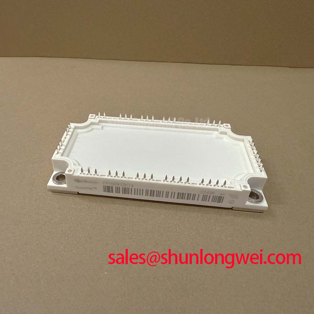
For a replacement review, compare 7MBR50SB120-55 by circuit topology, terminal arrangement, control requirements, thermal interface, and mechanical envelope. It is a comparison reference, not an asserted drop-in alternative. Electric material-handling equipment and forklift low-voltage traction systems are potential compatibility assessments only where the original converter architecture supports this module; the 1200 V rating alone does not establish suitability for that equipment.
Benchtop Waveform Tuning: Mitigating Electrical Stress and Evaluating Thermal Grease Pump-Out on 7MBP150RA120-14
Compare switching measurements at a controlled starting temperature and again after the assembly reaches repeatable thermal conditions. As a Design Consideration, a waveform change after warm-up should prompt checks of cooling, interface contact, driver supply, and load conditions before the module is condemned. Keep probe position and test settings consistent so that measurement differences do not masquerade as electrical deterioration.
Thermal grease pump-out is an interface concern associated with repeated movement between contacting surfaces during temperature cycling. Inspect for redistribution after the equipment's approved operating and service sequence rather than assuming fresh grease remains uniformly distributed. Where the mounting instructions specify progressive diagonal tightening, follow that sequence to promote even seating. The goal is controlled contact pressure without bending the package or overstressing the mounting structure; neither baseplate material nor internal substrate construction should be inferred from appearance.
Separate slow temperature drift from fast electrical stress. A deteriorating interface can raise operating temperature, while turn-off overshoot is strongly influenced by current-path inductance and switching behavior. Measure the terminal voltage during representative transitions and review the physical loop if the peak increases with current. Changes to damping or switching speed should be evaluated together with switching loss and thermal response, because reducing one waveform feature can increase another source of stress.
Freewheeling-diode recovery also deserves attention when the switching trace shows pronounced current or voltage ringing. Compare recovery-related waveform features at equivalent current, temperature, and switching conditions rather than assigning a softness factor from a scope image alone. Inspect probe-loop pickup and reference connections before attributing every oscillation to the semiconductor. Correlating power-terminal activity with the control input and fault output helps distinguish a genuine switching event from interference entering the measurement or control path.
For repetitive braking or acceleration pulses, assess heating with the manufacturer's transient thermal impedance information and the actual loss profile. Steady-state thermal resistance alone does not describe the temperature excursion during a short pulse. The The Advanced Thermal Management Revolution article provides background for reviewing heat-flow paths, but it does not establish the internal construction or mounting limits of 7MBP150RA120-14.
Close the bench record with the cold diode-path comparison, mounting procedure, thermal interface product, test conditions, and captured switching traces. If temperature continues to climb while electrical waveforms remain repeatable, investigate airflow, coolant delivery where applicable, heatsink cleanliness, and contact quality. If electrical stress changes without a corresponding cooling change, return to the commutation path and control timing. Those observations provide a defensible next repair action without reducing a complex fault to a single symptom-to-cause claim.