Content last revised on October 20, 2026
Benchtop Waveform Tuning: Mitigating Stress via Managing High C-Rate Battery Cycling Swing on 7MBP150VEA120-50
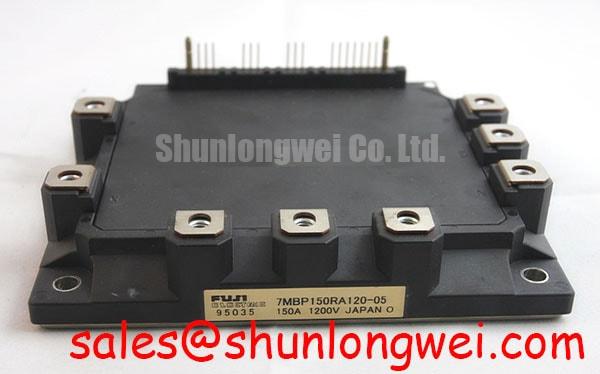
When a commercial string inverter reports an intermittent overcurrent or DC link disturbance during battery peak shaving, capture the battery rack current, inverter link voltage, and switching-node waveform before replacing the power module. The device under evaluation is the Fuji Electric 7MBP150VEA120-50, specified as a 1200.0 V, 150.0 A Fuji Power Module. These are official product specifications; they are not a complete operating limit for an assembled converter.
Four-quadrant power flow makes the bench test more demanding than a one-direction motor drive check. During charging, the inverter transfers energy from the AC side toward the battery rack. During discharge and peak shaving, the direction reverses, and the semiconductor switching pattern, DC-link ripple, and battery current slew all change. Regenerative transitions can expose different voltage overshoot and gate-control behavior from the same hardware operating point.
Use a controlled current profile that represents the intended battery-management command rather than applying an abrupt full-power step immediately. Compare the positive and negative power-flow transitions on the same time scale. A temperature probe or infrared camera can help identify whether a recurring event is associated with a switching position, a busbar connection, or a thermal accumulation pattern. Infrared measurements should be interpreted with suitable emissivity control and a clear view of the terminal and heatsink region.
The DC-link capacitor network deserves attention during this test. Film capacitors are commonly evaluated in high-ripple DC-link applications because ripple current, layout inductance, and capacitor temperature interact with switching stress. The film capacitor reference provides useful background for reviewing this part of the energy path. The practical task is to correlate capacitor ripple behavior with the measured module waveform, not to assume that a nominal bus voltage alone describes transient stress.
Keep the high-current commutation path compact and mechanically supported. Designers should minimize parasitic loop inductance to reduce turn-off voltage overshoot, then verify the resulting peak voltage against the application DC-link boundary during switching tests. Clearance around the power terminals should remain free of loose hardware, conductive debris, and cable movement that could alter the intended field distribution.
For a system-level comparison, engineers may also review the 7MBR100SB060-50 as a separate Fuji Electric module reference. It should be treated as an independent evaluation candidate, with pin arrangement, voltage class, current rating, mechanical fit, thermal interface, and gate-drive requirements checked against the original assembly before any substitution decision.
Benchtop Waveform Tuning: Mitigating Stress via Main Power Terminal Contact Resistance on 7MBP150VEA120-50
Terminal heating under continuous current should be investigated as a joint-quality problem before it is attributed to the silicon. Isolate the converter, discharge the stored energy according to the equipment safety procedure, and use a calibrated four-wire micro-ohmmeter across the bolted connection. A value below 10 µΩ may be used as a Design Consideration for auditing a clean, correctly assembled high-current joint, not as a published Fuji Electric limit for this model.
Measure the complete current path in sections. A reading taken across the module terminal alone can hide resistance at the busbar interface, washer contact, cable lug, fuse holder, or adjacent link. Repeat the measurement after mechanical inspection and compare equivalent phases or poles. A changing value after movement suggests that the joint geometry, surface condition, or clamping process requires correction.
Thermographic inspection should be performed with the converter carrying a representative load and with the camera positioned consistently. Compare the temperature profile of equivalent terminals, the nearby busbar, and the heatsink mounting region. A local hot area at one interface may justify torque and surface checks, while a broad temperature rise across all current paths may point toward airflow, switching loss, load imbalance, or inadequate thermal coupling.
Maintenance Note: monitor terminal temperature during scheduled load checks and clean the heatsink and air path before rising contact or case temperature becomes a shutdown event.
High-speed semiconductor fuse coordination belongs in the same review. The fuse clearing characteristic, its I²t behavior, available fault current, wiring inductance, and the module’s documented surge capability must be considered together. Do not treat a fuse rating as proof of protection for every short-circuit condition. The protection network should interrupt fault energy within the capability established by the module documentation and the converter test program.
For a battery inverter or micro-grid cabinet, inspect the fuse-to-module conductor route for unnecessary loop area and unsupported cable weight. Mechanical vibration can gradually alter a bolted joint, while repeated thermal cycling can change the pressure distribution at a busbar interface. The maintenance record should identify the measured location, operating current, ambient condition, and instrument used, so later readings remain comparable.
An upstream or auxiliary power stage can affect the waveform seen by the inverter bridge. The 2MBI150SC-120 may be reviewed as a separate power-stage reference when assessing rectification or auxiliary topology relationships. Its electrical and mechanical characteristics must be evaluated independently rather than assumed to match the 7MBP150VEA120-50.
Assembly Integrity & Layout Architecture: Implementing Transient Thermal Impedance for 7MBP150VEA120-50
Transient thermal impedance becomes important when a battery converter alternates between short peak-shaving bursts and lower standby power. The correct assessment begins with the actual pulse sequence, conduction pattern, switching frequency, coolant or airflow condition, and mounting interface. The 1200.0 V voltage rating and 150.0 A current rating identify the product class, but they do not replace a junction-temperature calculation for a particular duty cycle.
A practical thermal model can represent the junction-to-case path as a series of resistance and capacitance sections. Each section describes how quickly heat reaches the case and how much thermal energy is temporarily stored. Apply the measured or documented loss profile to that model, then compare the calculated junction trend with the applicable maximum junction temperature from the original technical documentation. The model is an Engineering Calculation and should be checked against measured case temperature during representative pulsed operation.
Mounting condition strongly influences the result. The heatsink surface should be clean, flat within the equipment manufacturer’s stated assembly tolerance, and free from old, dried, or uneven thermal interface material. Apply the selected interface material consistently across the contact area. Excess material can act as an additional thermal barrier, while incomplete coverage can create localized hot regions.
Layout architecture also controls the electrical and thermal result. Keep power conductors arranged symmetrically where the topology requires matched current paths, support heavy busbars independently from the module terminals, and prevent cable force from loading the case. Maintain the required creepage distance along insulating surfaces and the required clearance through air for the actual working voltage, pollution environment, altitude, and transient category. These distances are Design Considerations unless the original assembly drawing defines exact values.
High-side gate-drive isolation deserves a separate review. A digital isolator or optocoupler must tolerate the common-mode transient produced by the switching node, and its propagation delay must remain compatible with the controller’s dead-time and fault response. Designers should compare the isolator’s specified CMTI and timing behavior with the measured switching environment, then validate both turn-on and turn-off paths under the final gate-loop layout. Avoid routing isolated control traces beside high dv/dt collector or emitter conductors for long parallel distances.
Moisture control is part of assembly integrity in equipment exposed to low temperature, condensation, or repeated cabinet heating. Inspect enclosure seals, drain paths, conformal protection where specified by the equipment design, and signs of contamination around the power terminals. Do not add coatings or insulating films to an interface that requires a defined thermal or electrical contact without confirming material compatibility.
The industrial application background at Industrial Applications can support a broader review of IGBT use in renewable-energy and heavy-duty power systems. For this module, the immediate maintenance objective remains measurable: preserve the intended thermal path, control the commutation loop, and verify the assembled unit under its real pulse pattern.
Field Diagnostics & Commissioning: Mitigating Hard Switching Transients via Controlled Turn-Off in 7MBP150VEA120-50 Topologies
Hard-switching transient investigation should begin at the gate command, continue through the isolated driver, and end at the power-terminal waveform. A two-stage soft turn-off strategy can reduce the rate of current interruption during a fault, but its timing, gate voltage, driver current, and protection threshold are system-dependent. The inverter designer must validate the method against the module’s documented short-circuit behavior rather than treating a generic soft turn-off sequence as universally suitable.
Type-I and Type-II short-circuit conditions can produce different current development and detection behavior. A controller intended to identify a fault within 10 µs should be evaluated as a system response target, not presented as an official protection specification of the 7MBP150VEA120-50. Use a current probe with adequate bandwidth, observe the gate-emitter waveform at the module terminals, and account for propagation delay through sensing, isolation, logic, and gate-drive stages.
When a fault is detected, the first turn-off action should prevent an uncontrolled gate collapse from creating excessive inductive overshoot. A staged sequence may use an initial controlled reduction followed by a firm gate-off command, provided the driver, isolation channel, and module operating limits support that behavior. Verify the peak collector-emitter voltage, gate voltage, fault duration, and repeated-fault recovery behavior during a controlled commissioning test.
Overvoltage absorption should be coordinated rather than added as an isolated component. A MOV network, DC-link film capacitor, snubber, and semiconductor switching path each respond over different time scales. The MOV clamping level must be compatible with the DC-link operating range and the insulation coordination of the assembly. Its energy capability, thermal placement, aging behavior, and fault containment also require system-level review. No MOV arrangement should be described as an independent EMC certification for the module or the complete inverter.
Commissioning should include a low-energy verification phase before the battery rack is connected at full capability. Check the driver supply behavior, interlock status, fault reset logic, and current-sensor polarity first. Then increase operating demand while recording the switching-node waveform and thermal response. A recurring overshoot may indicate commutation-loop inductance, gate-loop interaction, sensor delay, or protection-network behavior; compare the signal against a known-good phase and inspect the physical routing before changing control parameters.
Delta-sigma current-sensing devices are often considered where galvanic isolation and noise immunity are required in industrial drives and energy converters. The delta-sigma modulation reference explains the conversion principle, while the selected sensing IC must still be checked for isolation rating, delay, bandwidth, CMTI, and fault-response integration within the actual controller.
For commercial string inverters and micro-grid energy-storage cabinets, final acceptance should record the installed module identity, busbar arrangement, gate-driver revision, protection settings, thermal interface condition, and measured waveform limits. The Fuji Electric 7MBP150VEA120-50 remains a 1200.0 V, 150.0 A Fuji Power Module; safe operation depends on how the complete power stage, mechanical assembly, isolation system, and transient protection are commissioned together.