

Content last revised on October 13, 2026
MG150J2YS50 Thermal-Electrical Optimization: Fault-Clearing Dynamics: Type-I/II Desaturation Tuning
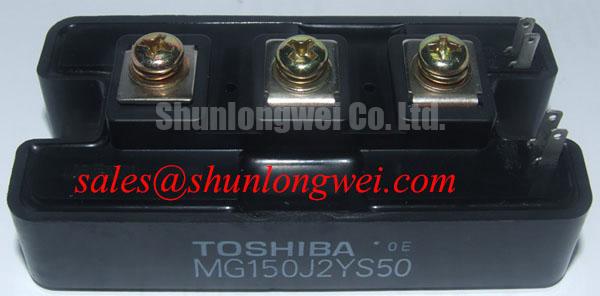
Check the terminal markings against the equipment schematic before connecting test leads: MG150J2YS50 | Manufacturer: Toshiba | Official Specification: 600 V, 150 A | Package: Toshiba Module | Pin assignments, rating conditions, and insulation test limits: consult the manufacturer datasheet.
I separate the module from the driver circuit before checking gate-to-emitter behavior, because an attached discharge resistor can dominate a cold resistance measurement. For the Toshiba MG150J2YS50 IGBT module, incoming inspection should begin with terminal polarity and circuit-symbol correspondence, not an assumed pin arrangement. Where the manufacturer circuit diagram identifies a reverse diode, record its diode-mode response in both directions using the same meter and temperature conditions as the comparison device. A reading is a screening observation, not proof of full-current switching capability.
Design Consideration: distinguish a Type-I fault, where the switch turns on into an existing short circuit, from a Type-II fault that develops during conduction. These conditions can produce different collector-voltage and gate-voltage trajectories. Evaluate desaturation blanking, sensing delay, driver propagation, and shutdown together; a generic microsecond target is not an established short-circuit withstand specification for this model. Fault testing belongs on a controlled, energy-limited fixture with appropriate containment.
Engineering Recommendation: where the driver supports staged shutdown, assess an initial controlled gate discharge followed by secure gate clamping. The objective is to reduce the current interruption rate without extending fault energy beyond the validated device boundary. Capture collector-emitter voltage, gate-emitter voltage, and fault indication on a common time reference. Excessive overshoot can involve wiring inductance, sensing delay, or gate discharge behavior rather than a single failed component.
Design Consideration: semiconductor fuse coordination is a separate protection task. Compare the fuse manufacturer’s total clearing I²t and interrupting capability with the equipment’s prospective fault current and validated protection requirements. A fast fuse should not be treated as a substitute for electronic short-circuit detection, nor should its presence imply guaranteed module survival.
Preventing Spurious Faults: Separating Driver Return from Main Current Guidelines for MG150J2YS50
Trace the driver return to its actual module connection before attributing nuisance trips to the desaturation circuit. Design Consideration: shared emitter-path inductance can shift the driver’s local reference during current transitions, changing the effective gate-emitter voltage. Identify any dedicated auxiliary emitter connection from the manufacturer terminal drawing; do not infer a Kelvin terminal from the package appearance or a neighboring Toshiba model.
Engineering Recommendation: keep the gate-drive outgoing and return conductors closely associated, and avoid routing the driver return through the load-current path. Measure gate-emitter voltage at the relevant module terminals with a suitable differential probe. Compare that trace with the driver-side signal to distinguish commanded switching from reference movement. Probe-loop pickup can resemble ringing, so repeat suspicious captures with a shorter measurement loop before modifying the circuit.
Design Consideration: on an isolated driver board, evaluate the optocoupler or digital isolator against its own common-mode transient immunity specification. Correlate unexpected output transitions with switch-node edges and local supply disturbance. If a bootstrap supply is present in the equipment schematic, assess capacitor discharge during the longest commanded on-state, recharge opportunity, and bootstrap-diode recovery. These are driver-circuit checks, not built-in features of the MG150J2YS50.
When following the upstream power path, review any phase-angle-controlled rectifier, line-frequency ripple filtering, and RC snubber against the equipment schematic. Those functions belong to their respective stages. The MG30G2CL3 is a separate module for independent topology and rating assessment, not an assumed rectifier companion. The external discussion of interleaved boost converters explains ripple cancellation in that topology; it does not establish an interleaved architecture or ripple specification for this Toshiba module.
MG150J2YS50 Circuit Protection & Reliability: Oscilloscope Waveform Verification
Capture the existing gate and collector waveforms before changing turn-on or turn-off resistance during a board repair. Engineering Recommendation: preserve the original driver configuration as the comparison baseline, then evaluate changes under controlled bus voltage, load, and temperature conditions. Separate turn-on and turn-off resistors affect different transitions; their values should follow measured switching behavior and driver capability rather than a universal retrofit recipe.
Design Consideration: slower gate transitions can reduce some ringing while increasing switching dissipation. Faster transitions can expose parasitic coupling or protection-sensing problems. Observe collector overshoot, gate excursion, current transition, and driver supply stability together. Verify probe compensation, channel timing alignment, bandwidth settings, and common-mode operating limits before treating small waveform differences as device behavior.
For a repair-parts comparison, place MG150J2YS11 alongside MG150J2YS50 in the evaluation worksheet without treating the similar designation as proof of interchangeability. Compare terminal mapping, mounting geometry, gate characteristics, diode behavior, thermal limits, and switching test conditions. A shared voltage or current class alone does not authorize substitution on an existing drive board.
Bench Tip: With the power circuit discharged and isolated, use ESD precautions and identical meter conditions when comparing cold-state readings against a documented reference device.
Engineering Recommendation: retain those readings with the waveform captures and assembly observations so later troubleshooting has a reproducible baseline. The Industrial Applications overview provides broader application context, but acceptance limits should come from the component specification and equipment test procedure, not generalized lifetime expectations.
MG150J2YS50 Operational Boundaries: Optimizing Gate-Drive Loop Geometry
Inspect the complete gate-return route across the connector, driver board, and module interface rather than judging the visible gate wire alone. Design Consideration: separating the signal return from the high-current emitter path reduces shared impedance; a dedicated auxiliary connection should be used only where the terminal drawing explicitly identifies it. Check adjacent channel routing as well, since coupled switching transients can disturb another driver’s reference.
Engineering Recommendation: assess conductor spacing and insulation coordination from the equipment working voltage, pollution conditions, insulating materials, and applicable system requirements. For incoming insulation testing, distinguish power-terminal-to-baseplate isolation from collector-emitter blocking. The 600 V electrical rating is not a baseplate dielectric test voltage. Use the specified electrode grouping, test method, and acceptance limits rather than applying an improvised high-voltage screening test.
Design Consideration: inspect the mounting surface and thermal interface for contamination, uneven contact, and assembly damage before interpreting temperature rise. The external reference on sintering explains a general materials process; it does not identify the MG150J2YS50 die-attach material or justify a package-specific thermal claim.
For electric material-handling equipment or low-voltage forklift traction repair, designers should evaluate the 150 A rating under its specified conditions alongside the existing controller’s losses, cooling arrangement, and gate drive. Record connector alignment, terminal clearance, return routing, and measured switching behavior before accepting the assembly for the equipment’s controlled functional test.