Content last revised on October 11, 2026
Transient Dynamics & Electrical Design: Transient Thermal Impedance on MG150Q2YS91
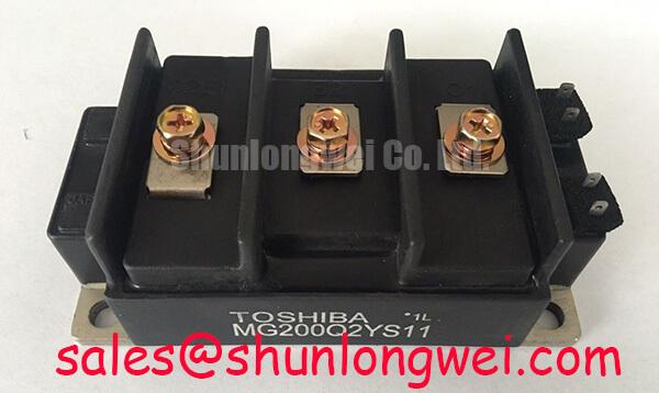
With the DC link isolated and discharge verified, compare the module marking with the equipment service record before reconnecting the power terminals or gate wiring. The Toshiba MG150Q2YS91 is an IGBT module with a specified voltage rating of 1200 V and rated collector current of 150 A under the specified datasheet conditions. Record the installed terminal arrangement and mounting condition so that electrical compatibility and thermal contact can be assessed together.
For the MG150Q2YS91, these ratings establish the initial identification boundary. Pin assignments, dimensional drawings, rating conditions, transient thermal curves, and short-circuit limits belong in the equipment compatibility review: consult the Toshiba datasheet for those details before approving installation.
Capture the overload duration, repetition pattern, and case temperature before assessing a pulsed thermal event. As a Design Consideration, a heatsink temperature reading alone cannot represent the junction temperature during a brief overload: heat reaches the case and heatsink on different timescales. Correlate the load record with measured or appropriately characterized semiconductor losses rather than treating output current as a direct temperature measurement.
An Engineering Calculation can express the response to a constant loss pulse as junction temperature rise ΔTj(t) = P × Zth(j–c)(t), where P is the pulse loss and Zth(j–c) is the applicable junction-to-case transient thermal impedance. A multi-RC model fitted to the manufacturer's thermal response can extend that calculation to changing losses and repeated pulses through time-domain superposition. Preserve the distinction between Foster and Cauer networks; their internal nodes are not interchangeable physical temperature locations.
For practical MG150Q2YS91 integration, use the resulting peak junction estimate alongside the measured case temperature and the manufacturer's junction limit. Include residual heat from preceding pulses. A cooling assembly that recovers between isolated events can behave differently under repeated overloads, even when each event has the same peak current.
Inspect the baseplate contact surface, mounting flatness, and thermal interface condition during the same outage. As an Engineering Recommendation, investigate uneven case heating against airflow, contact quality, and loss distribution before attributing it to the semiconductor. Establish thermal interface inspection intervals from equipment duty and recorded temperature trends, not an invented module service-life figure.
MG150Q2YS91 Thermal-Electrical Optimization: Derating Guidelines and Parameter Mismatch Practical Tuning
Build the thermal operating assessment from conduction losses, switching losses, and the actual cooling path at each intended operating point. As a Design Consideration, increasing switching frequency increases the number of switching events, while ambient temperature and restricted airflow reduce heat-removal capability. Evaluate the equipment's own frequency range rather than assigning the MG150Q2YS91 an unsupported frequency rating or a universal current-derating curve.
Where the circuit parallels switching devices, examine the temperature dependence of collector-emitter saturation voltage at the relevant current and gate conditions. A positive coefficient can assist steady-state current sharing within an applicable operating region, but it must not be assumed across all currents or declared a verified MG150Q2YS91 characteristic without its curves. Dynamic sharing also depends on gate-loop impedance, propagation delay, power-path inductance, and thermal asymmetry.
Keep cooling comparisons tied to measurements made under comparable load conditions. Check inlet blockage, fan operation, exhaust recirculation, and terminal heating separately. Maintenance Note: Trend terminal and case temperature under comparable loads, and check cooling airflow during scheduled maintenance before increasing the operating load. In environments with temperature cycling, inspect for moisture and condensation before re-energization; cabinet humidity control remains an equipment-level responsibility.
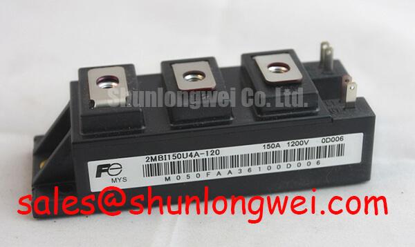
During replacement assessment, compare MG150J2YS11 against the installed MG150Q2YS91 using terminal mapping, mechanical fit, switching characteristics, thermal data, and driver compatibility. Its related model designation is not evidence of direct interchangeability. Approval should follow the equipment's documented compatibility process rather than voltage and current labels alone.
MG150Q2YS91 Circuit Protection & Reliability: Calibrating Bi-Directional DC-DC Buck-Boost Conversion
Map commanded current direction, commutation paths, and fault responses before calibrating a bidirectional converter. As a potential compatibility assessment, commercial string inverters and micro-grid energy-storage equipment may require evaluation of the MG150Q2YS91 within a battery-to-link conversion stage. Bidirectional energy transfer does not itself establish four-quadrant voltage-and-current capability; that depends on the complete topology and control arrangement.
As a Design Consideration, check regenerative operation and load transitions for repeated thermal excursions, not just maximum steady load. Compare current measurements, gate commands, and DC-link behavior during controlled transitions. Review the function of each complementary stage separately; MG30G2CL3 can be included in that circuit review, but its rectification or switching role must follow its own specifications and the equipment schematic.
Desaturation protection should be assessed as a complete chain: collector-voltage sensing, blanking, detection delay, driver response, and controlled turn-off. Soft turn-off can reduce inductive overvoltage during fault interruption, while excessive delay increases semiconductor stress. Establish those settings against documented device short-circuit capability and measured system behavior, without assigning this module an unsupported withstand time or short-circuit safe-operating-area limit.
Semiconductor fuse coordination requires the fuse's clearing behavior and let-through energy to be evaluated against the actual fault circuit. An I²t comparison alone does not guarantee transistor survival or containment of a destructive fault. Review prospective fault current, DC interruption capability, bus inductance, and upstream isolation with the equipment protection design; do not treat a fast fuse as a substitute for gate-level fault response.
MG150Q2YS91 Thermal-Electrical Optimization: PCB Symmetry Considerations for Dual IGBT Practical Tuning
Trace the gate-driver return on the schematic and installed wiring before changing PCB routing. As a Design Consideration, shared emitter-path inductance can introduce feedback into the gate voltage during rapid current transitions. Where the verified terminal diagram provides a separate auxiliary emitter connection, route its driver return separately from the main power-current path; do not assume the MG150Q2YS91 provides a Kelvin emitter terminal.
Match comparable gate paths in geometry and impedance where the circuit requires balanced switching. Keep high-current commutation paths away from sensitive sensing returns, and determine clearances from working voltage, insulation requirements, and the equipment's applicable design rules. Examine gate ringing with suitable differential probing, distinguishing real oscillation from probe-loop pickup before modifying damping components.
Evaluate optocoupler or digital-isolator common-mode transient immunity against the switching node's measured behavior. False pulses can involve isolator immunity, supply disturbance, grounding, or layout coupling. The discussion in Unlocking Efficiency in Industrial Drives provides broader switching context, not evidence that MG150Q2YS91 uses that technology. Likewise, ROHM Field Stop Trench IGBTs & Intelligent Modules describes a separate manufacturer's products.
If temperature feedback is present in the equipment, identify the sensor and its location before interpreting readings. The NTC thermistor operating principle explains decreasing resistance with rising temperature, but does not establish an internal sensor in this module. Finish driver validation by correlating gate voltage, collector voltage, and current during controlled switching and protection tests, retaining those waveforms as the maintenance reference.