


Content last revised on September 10, 2026
7MBR150XRE120-50 Thermal Electrical Optimization: Overvoltage Trip Prevention via Fast Switching Practical Tuning
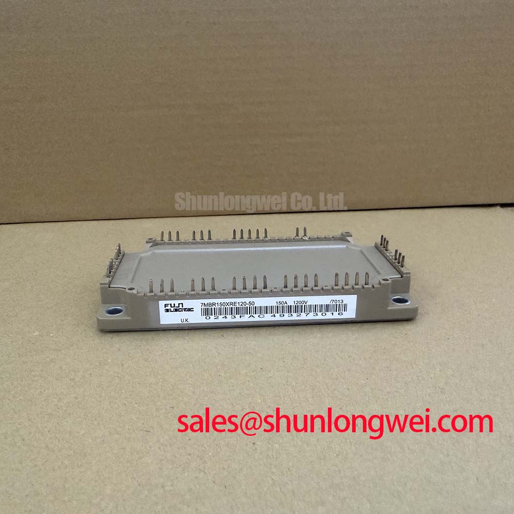
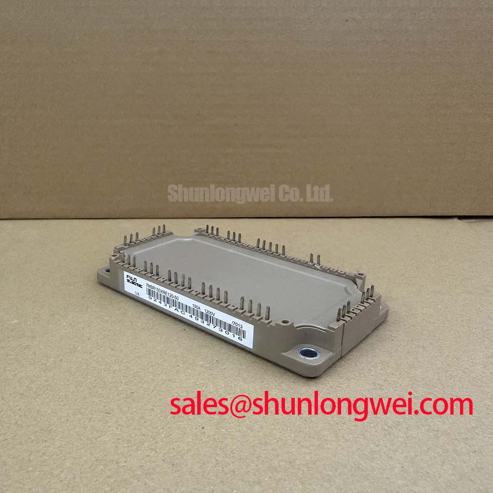
Before fitting a replacement module, isolate the equipment, discharge the DC link according to the machine service procedure, and verify that the module markings match 7MBR150XRE120-50 before reconnecting any gate or power terminals. This Fuji Electric power module is rated at VCES 1200 V with specified collector-current ratings of 150 A continuous and 300 A pulsed for 1 ms, under the applicable datasheet conditions. Its converter stage is rated at VRRM 1600 V and 150 A forward current.
In an inverter welder or medium frequency induction heating supply, DC link voltage can rise during rapid load energy return, switching interruption, or unstable braking control. The module rating establishes the electrical boundary, but the braking path, ballast resistor energy capability, DC link capacitance, cable inductance, and controller trip threshold remain system determined. Engineers should confirm from the original circuit documentation whether the equipment uses an internal braking function, an external braking transistor, or a separate regenerative arrangement before assigning a replacement module to that function.
As a Design Consideration, keep the commutation loop between the DC link capacitors, module power terminals, and braking path physically compact. This reduces inductive voltage overshoot when current is interrupted. A high energy resistor must also be assessed for its pulse energy, cooling path, wiring clearance, and enclosure temperature rather than selected from resistance value alone. During commissioning, capture DC link voltage and switching waveforms using suitably rated differential measurement equipment, then verify peak conditions against the system voltage boundary.
When investigating nuisance overvoltage trips, inspect capacitor connections, braking resistor terminals, contactor condition, control timing, and the routing of high current conductors. A waveform that changes after cable replacement or terminal maintenance may indicate loop inductance or connection quality rather than a fault in the IGBT module itself. For topology context, engineers maintaining related converter sections can compare the interface requirements of the 7MBR35UA120 with the original equipment drawings. The energy transfer principles involved in step up converter circuits are also described in this Boost Converter Step Up DC DC Conversion Principles reference.
Preventing Spurious Faults: Baseplate Thermal Grease Layer Control Guidelines for 7MBR150XRE120-50
The 7MBR150XRE120-50 has a maximum specified junction temperature of up to 175°C and an isolation voltage of 2500 Vrms for A.C. one minute. These values do not remove the need to inspect the heatsink surface, mounting flatness, thermal interface material condition, and electrical isolation arrangement in the installed assembly.
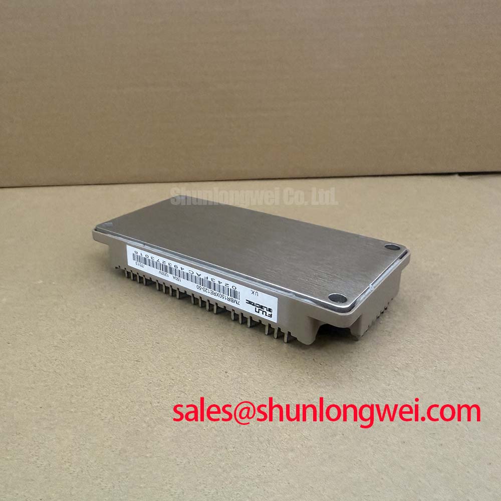
A thin and continuous thermal interface layer helps transfer heat while avoiding dry contact regions and trapped air. A 50 to 100 μm grease layer is a General Industry Design Consideration where the heatsink finish, flatness, and module mounting instructions allow it. The correct result is controlled coverage rather than simply applying more compound. If the baseplate or heatsink has visible distortion, corrosion, residue, or a localized witness mark from a previous installation, correct that mechanical condition before judging thermal performance.
Mounting screws should be tightened progressively in a balanced sequence so the baseplate settles evenly. The exact screw type, thread engagement, torque, insulation hardware, and sequence must follow the module mechanical documentation and the equipment manufacturer’s service instructions. ⚠️ Maintenance Note: Periodically monitor terminal and heatsink contact temperature rise while checking that the cooling air path remains clear of dust and obstructed filters.
Desaturation protection belongs to the gate driver and surrounding system, not to the published rating list for this module. As an Engineering Recommendation, designers should verify that the desaturation sensing interval, blanking logic, fault reporting, and soft turn off behavior are coordinated with the actual switching waveform. A protection response that is too slow can increase semiconductor stress, while one that is too sensitive can react to legitimate transient behavior. Oscilloscope checks should compare gate emitter voltage, collector emitter voltage, and current sensing against a known healthy operating condition.
Transient Dynamics & Electrical Design: Thermal Feedback on 7MBR150XRE120-50
Temperature affects IGBT conduction characteristics, switching loss, and current distribution in paralleled power paths. The positive temperature tendency of VCE(sat) can support steady state static current sharing under suitable matched conditions, but it does not guarantee dynamic sharing during switching. Symmetrical power routing, equivalent gate drive paths, consistent connector condition, and comparable cooling conditions remain important Design Considerations.
For systems using parallel modules or parallel current paths, compare physical routing before changing driver components. Unequal gate loop length, uneven emitter return paths, mismatched gate resistance, or different heatsink conditions can alter the turn on and turn off sequence. The system engineer should verify current sharing with appropriate current measurement methods under representative load and temperature conditions rather than relying on static measurements alone.
The thermal impedance network of the module and heatsink determines how a pulse load affects junction temperature. A short load event can create a transient junction rise that is not visible immediately at the heatsink. For this reason, maintenance teams should review switching events, load duty cycle, airflow condition, and the quality of the thermal interface together. The published 175°C maximum specified junction temperature is an Official Datasheet Specification, while allowable pulse loading must be evaluated against the complete equipment duty cycle and manufacturer curves.
For broader discussion of switching technologies and their integration tradeoffs, the Wide Bandgap Revolution engineering guide provides useful context. It should not be treated as a direct replacement recommendation for this Fuji Electric module. Where a different current class is under formal engineering review, the 6MBI450U-120A-05 can be examined against the original electrical, mechanical, cooling, and driver requirements.
7MBR150XRE120-50 Operational Boundaries: Evaluating Gate Drive Loop Geometry to Prevent Limits
Gate drive loop geometry directly affects switching stability. The gate signal and its emitter reference should return through a controlled, low inductance path that is separate from the main high current emitter route wherever the module terminal arrangement and original driver design provide that option. This Design Consideration reduces common emitter inductance effects that can otherwise disturb the effective gate voltage during rapid current change.
Do not assume terminal functions from package appearance alone. Before service work, use the original module connection diagram and equipment schematic to identify power, gate, auxiliary emitter, converter, and sensing connections. Confirm continuity of harnesses, plugs, crimp joints, and driver board connections while power is removed. A gate waveform with ringing, unexpected plateau movement, or irregular turn off behavior may indicate coupling, grounding, driver supply disturbance, or probing error; verify the signal path with a suitable oscilloscope setup.
Long motor cables can introduce reflected voltage at the motor end and alter the inverter’s transient environment. Cable length, motor insulation condition, output filtering, grounding arrangement, and switching pattern must be assessed as a complete system. Designers should verify measured peak voltage margins during switching tests and apply the equipment manufacturer’s specified output filtering approach where required.
Protection coordination should also include semiconductor fuses and fault interruption hardware. Fuse suitability depends on the actual prospective fault current, interruption duty, coordination with contactors or breakers, and the module’s application conditions. The general framework for semiconductor converter equipment can be reviewed through IEC 60146 Semiconductor Converters Standard. This reference supports system level evaluation and does not assign a standalone compliance status to the module.