Content last revised on September 10, 2026
DC-Bus Operating Voltage Headroom Derating for Single Event Burnout (SEB) Immunity
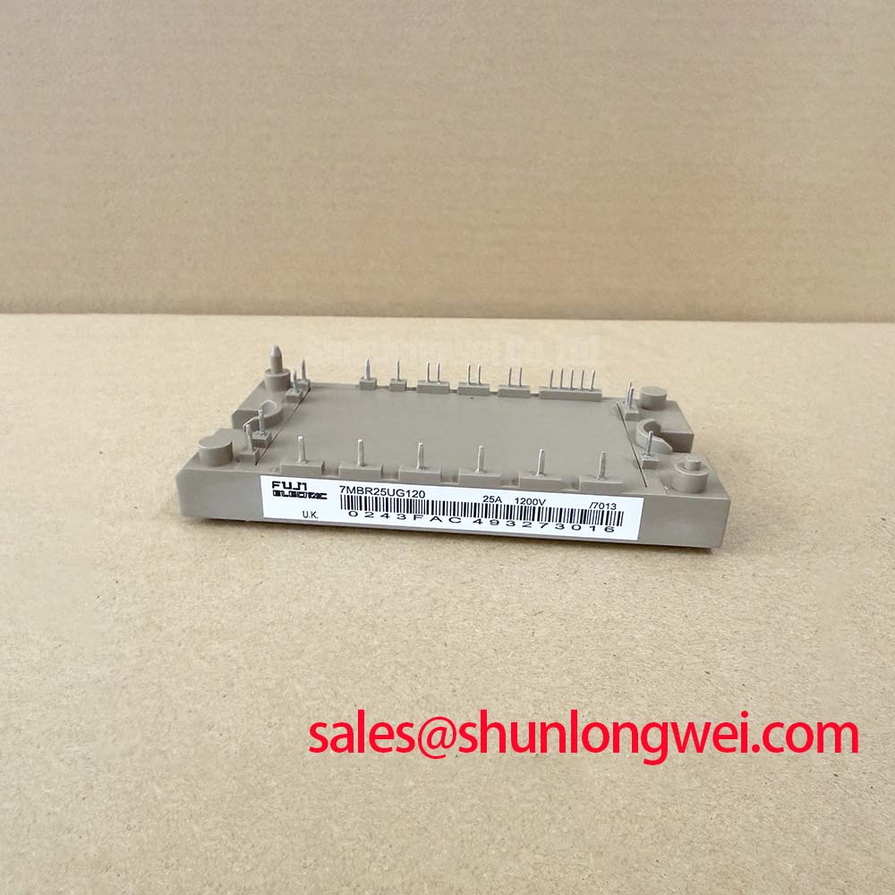
In multi-joint robotic articulator drives deployed across light industrial assembly lines, incoming quality assurance for power modules like the 7MBR35SB120 begins at the test bench. Rated at a maximum collector-emitter voltage of VCES = 1200V (Official Datasheet Specification) with a continuous collector current rating of IC = 35A at TC = 80°C (Official Datasheet Specification), this compact Power Integrated Module (PIM) integrates a three-phase input bridge, brake chopper, and inverter stage. When qualifying incoming units for high-altitude or continuous-duty factory installations, engineering teams must factor in terrestrial cosmic ray neutron flux, which significantly increases Single Event Burnout (SEB) risks if the continuous DC-bus voltage is held too close to the silicon breakdown limit.
For installations operating above 2000 meters sea level, empirical field guidelines from Fuji Electric Global Power Semiconductor Technologies recommend maintaining the steady-state DC-bus voltage between 550V and 650V (Design Consideration for terrestrial neutron derating) rather than running near the nominal 800V ceiling. During incoming static screening, our QA bench measures collector-to-emitter leakage current (ICES) at 25°C under rated 1200V blocking conditions to ensure baseline silicon integrity before deployment. Engineers evaluating multi-axis servo designs can consult the Field Engineer’s Handbook for detailed isolation breakdown thresholds and high-altitude derating curves.
💡 Bench Tip: When performing cold static checks with a digital multimeter on the diode test setting, the integrated freewheeling diodes across the lower and upper arms should consistently exhibit a forward voltage drop between 0.42V and 0.65V at room ambient temperature. Any arm showing an open circuit or anomalous reverse leakage below 10 MΩ at 500V DC indicates gate-oxide or p-n junction stress from improper handling.
Evaluating Thermal Capacitance vs Heat Sink Time Constant under Surge Bursts
During rapid trajectory acceleration in multi-joint robotic arms, the inverter stages experience short, severe current bursts. The 7MBR35SB120 features an internal total power dissipation rating of PC = 180W per IGBT at TC = 25°C (Official Datasheet Specification) and operates across a junction temperature range of Tj = -40°C to +150°C (Official Datasheet Specification). Under high-torque dynamic moves lasting under 50 milliseconds, the thermal capacitance of the silicon die absorbs the heat before the copper baseplate and external heat sink reach thermal equilibrium.
Calculating peak junction temperature during these bursts requires accounting for the module's transient thermal impedance characteristics. Bench technicians verify thermal interface integrity by monitoring the forward saturation voltage, which specifies a maximum of VCE(sat) = 2.7V at IC = 35A and Tj = 125°C (Official Datasheet Specification). When matching the module with system requirements, designers often evaluate drive architectures: for sub-fractional auxiliary rectifiers or intermediate power conversion stages, the dual-pack 2MBI150-060 serves as a baseline comparison for low-voltage auxiliary topologies.
| Parameter Description | Official Datasheet Value | Condition / Context | QA Verification Method |
|---|---|---|---|
| Collector-Emitter Voltage (VCES) | 1200V | Tj = 25°C | High-voltage leakage tester (ICES < 1.0mA) |
| Continuous Collector Current (IC) | 35A | TC = 80°C | Load bench thermal equilibrium test |
| Collector Saturation Voltage (VCE(sat)) | 2.7V (Max) | IC = 35A, VGE = 15V, Tj = 125°C | Pulsed curve tracer static bench test |
| Gate-Emitter Voltage (VGES) | ±20V | Continuous rating | Gate leakage current verification (IGES) |
| Short-Circuit Withstand (tsc) | ≥ 10µs | VCC = 600V, VGE ≤ 15V, Tj = 125°C | Factory type-tested dynamic qualification |
Thermal Cycling Margins of Internal Braking IGBTs under Repetitive Stop-Start Duty
High-speed pick-and-place robots place intense repetitive loads on the internal brake chopper circuit of the 7MBR35SB120. Each time a mechanical axis halts, regenerated kinetic energy feeds back onto the DC bus, triggering the brake IGBT to discharge excess voltage across an external dynamic braking resistor. Over millions of cycles, the solder layers connecting the silicon die to the Direct Copper Bonded (DCB) ceramic substrate undergo thermal mechanical shear strain.
To preserve long-term reliability in repetitive cycling applications, keeping the cyclic thermal excursion (ΔTj) below 40°C is an established design practice (General Industry Design Consideration). Bench inspection of used or qualified incoming units focuses on measuring baseplate flatness across the mounting plane (recommended flatness tolerance < 50µm) to prevent void formation in the thermal interface material (TIM). For larger multi-axis cabinets requiring centralized braking and higher output currents, engineers frequently compare power scalability with higher-capacity inverter topologies like the 7MBI100U4E-120-50 to balance thermal loading across separated modules.
⚠️ Field Alert: When mounting the module to a machined aluminum heat sink, apply a uniform layer of non-curing thermal grease with a thickness of 60µm to 100µm (Typical Starting Point for planar heatsinks). Tighten the M5 mounting screws sequentially using a pre-torque of 1.0 N·m followed by a final tightening torque of 2.5 to 3.5 N·m (Standard Industry Design Consideration for M5). Uneven torque distribution can crack the internal ceramic substrate or induce localized hot spots during active braking cycles.
Common-Mode Transient Immunity (CMTI > 100kV/us) in Harsh Industrial Environments
Industrial robotic arms operating alongside high-frequency welding or plasma-cutting equipment are exposed to extreme electromagnetic transients. High dV/dt switching slew rates generate parasitic displacement currents through gate driver isolation barriers, potentially causing unintended gate turn-on and catastrophic DC-bus shoot-through. The 7MBR35SB120 provides a robust short circuit withstand time of tsc ≥ 10µs under test conditions of VCC = 600V, VGE ≤ 15V, and Tj = 125°C (Official Datasheet Specification), offering sufficient response margin for primary desaturation detection circuits.
To maintain stable switching behavior, gate driver boards paired with this module should utilize optocouplers or digital isolators rated for Common-Mode Transient Immunity (CMTI) exceeding 100kV/µs (Design Consideration for industrial automation). On the bench, our QA technicians verify that the gate threshold voltage (VGE(th)) falls strictly within the nominal factory window of 5.5V to 8.5V at IC = 35mA. Ensuring symmetric turn-off via a negative gate bias (-5V to -8V) provides additional protection against false turn-on triggered by high parasitic dV/dt cross-coupling across the internal terminal connections.