

Content last revised on October 9, 2026
UM150CDY-10 Thermal Electrical Optimization for Pulsed Drive Loading
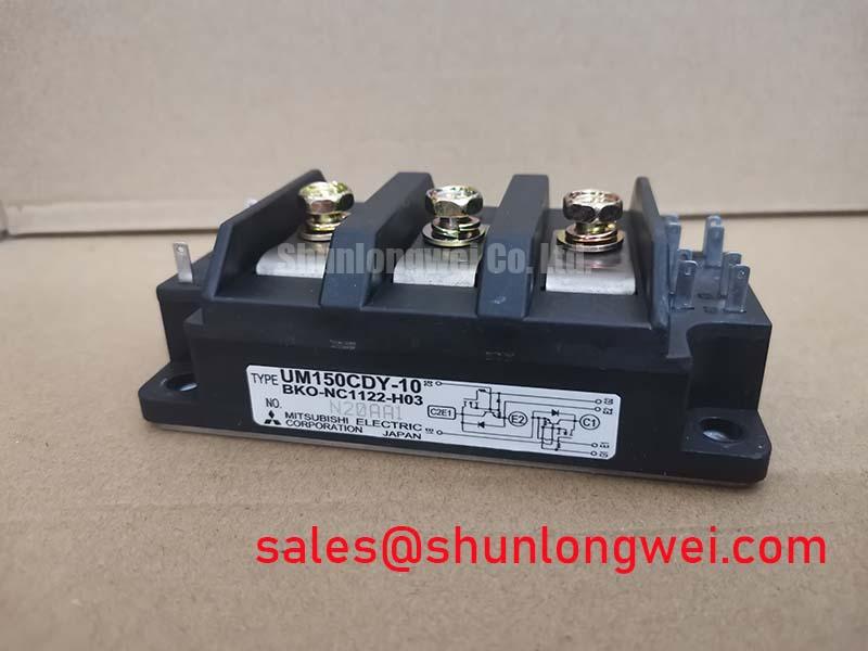
Measure the heatsink contact temperature and inspect the switching load profile before evaluating the UM150CDY-10 in a heavy duty variable frequency AC motor drive. Its official factory ratings are 600.0 V and 150.0 A, while the actual junction temperature during acceleration, deceleration, and overload depends on conduction loss, switching loss, cooling conditions, and pulse duration.
A transient thermal model is useful when the drive produces repeated current pulses rather than steady motor torque. The thermal network should represent the junction to case path, the interface material, the heatsink, and the surrounding airflow path. A multi RC model can then relate each load pulse to a temporary junction temperature rise. This is an engineering calculation, not an additional factory rating. The thermal resistance and transient impedance values used in that calculation must match the applicable Mitsubishi Electric documentation for the exact module variant.
In the service bay, compare the temperature rise at the module case with the heatsink inlet and outlet conditions. A rising case temperature with clean electrical waveforms can point toward deteriorated thermal transfer, blocked airflow, uneven mounting, or an overloaded cooling system. A temperature rise concentrated during switching transitions requires attention to gate drive behavior, commutation layout, and voltage overshoot rather than relying on the 150.0 A nominal current alone.
Designers should minimize the high current commutation loop and keep the DC link connection physically compact. During testing, use an appropriately rated differential probe and verify peak collector emitter voltage, current sharing, and case temperature under the real acceleration profile. The Mitsubishi Electric NX Series IGBT Modules documentation provides useful manufacturer context for evaluating power module construction and switching behavior, but it should not be treated as a substitute for the specific data applicable to this model.
UM150CDY-10 Operational Boundaries with Long Motor Leads
Check the motor cable length, cable construction, grounding arrangement, and measured terminal waveform before applying the UM150CDY-10 to a drive with long motor leads. A motor cable behaves as a transmission line at fast switching edges, and impedance mismatch can reflect part of the pulse back toward the inverter output. Under some installation conditions, the terminal voltage can approach twice the inverter output pulse voltage as a design consideration; the actual peak must be confirmed by measurement at the module and motor terminals.
Output reactors, dv/dt filters, or sine wave filters may be considered when the reflected wave stresses the motor insulation or the inverter switching devices. Their selection is system dependent. The drive engineer should evaluate the filter’s effect on switching loss, common mode current, motor torque response, protective trips, and thermal loading before installation. Do not select a filter solely from the 600.0 V module rating.
Switching frequency also changes the balance between motor acoustic behavior, semiconductor switching loss, and heatsink demand. A drive operated across a wide frequency range should be tested at the highest intended carrier frequency, maximum sustained motor current, and the worst expected ambient condition. Airflow should be checked at the heatsink inlet rather than assumed from the fan nameplate. Dust accumulation on fins and recirculation inside the cabinet can reduce cooling performance without creating an immediate electrical alarm.
For the upstream power path, engineers may evaluate the neutral CPT600150A product information alongside the rectifier and DC link topology. It is a related component reference, not an automatic substitute or guaranteed companion part. The complete power stage still requires voltage, current, commutation, protection, and thermal verification as one system.
Transient Dynamics and Baseplate Installation Practice
Prepare the heatsink surface, inspect the module baseplate, and apply the thermal interface material evenly before tightening the mounting hardware. A practical installation target for a conventional interface layer is typically established by the system mechanical design; the correct thickness, spread pattern, and material must be selected from the approved assembly process rather than assumed from the module’s electrical ratings.
Baseplate flatness and local heatsink distortion influence the pressure distribution across the interface. Excessive compound can trap air and increase thermal resistance, while insufficient material can leave dry regions beneath the baseplate. When a replacement module is installed, remove old compound, clean the mating surfaces with an approved process, and inspect for burrs, raised edges, or contamination around the mounting points.
Screw tightening should follow a diagonal or staged sequence so that the baseplate settles progressively instead of bending toward one fastener. The final torque is a design consideration determined by the module mechanical drawing, screw size, washer arrangement, heatsink material, and assembly standard. If the original equipment documentation specifies a torque, use that value and document the calibrated tool used during service.
After assembly, allow the interface to settle according to the compound manufacturer’s process, then check the thermal response under a controlled load. Uneven temperature across the heatsink can justify a second inspection of contact pressure and surface flatness. Keep the power terminals mechanically supported by the busbar structure so that cable forces do not transfer into the module housing or terminal joints.
⚠️ Maintenance Note: During scheduled service, clean the heatsink and verify contact temperature, fan airflow, and terminal tightness before returning the drive to continuous duty.
UM150CDY-10 Dynamic Braking Chopper Integration
Start dynamic braking evaluation by measuring the motor inertia, deceleration profile, duty cycle, and DC link voltage rise. The braking IGBT and ballast resistor must absorb the kinetic energy that the motor returns to the DC link, with the resistor converting that energy into heat. The UM150CDY-10 voltage and current ratings provide device selection boundaries, but they do not by themselves define allowable braking duration or resistor capacity.
Resistor sizing is an engineering calculation based on regenerated energy, braking frequency, pulse duration, resistor thermal mass, and the cooling arrangement. The braking controller must coordinate its switching threshold with the drive’s DC link protection so that resistor operation does not become continuous under a fault or an incorrectly configured ramp. Designers should verify the voltage waveform at the module terminals and confirm that switching overshoot remains within the applicable device limits.
Pay close attention to the busbar geometry between the DC link, braking device, and resistor connection. Minimize the power loop area to reduce parasitic inductance and turn off overshoot, then confirm the result with a properly rated oscilloscope probe during a controlled deceleration test. Gate resistor selection, dead time, snubber placement, and protection timing remain system design variables and should be tuned against measured waveforms rather than copied from an unrelated inverter.
For field troubleshooting, compare the DC link rise during an unloaded stop, a normal production stop, and the most demanding permitted deceleration. A mismatch between commanded ramp time and measured voltage rise may involve braking control, resistor thermal limitation, motor load variation, or sensor scaling. Record the event waveform before replacing the power module. The Field Engineer’s Handbook offers additional test and failure analysis reference material for this type of service work.
Where a different semiconductor technology is being considered for a future redesign, the Mitsubishi Electric SiC power module information can provide a neutral comparison point for switching behavior and system tradeoffs. It should not be interpreted as a direct replacement recommendation for the UM150CDY-10.