

Content last revised on October 5, 2026
Transient Dynamics & Electrical Design: Desaturation Detection on BSM150GD60DLC
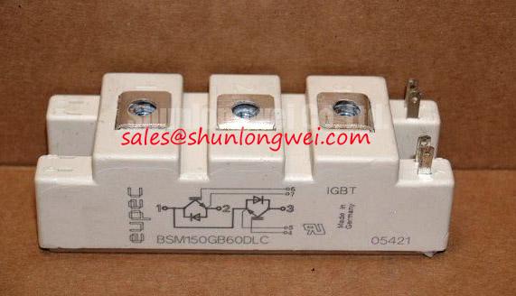
BSM150GD60DLC | Infineon | IGBT Module | Rated voltage: 600 V | Rated current: 150 A | Package: Module. These specification values do not establish the permissible DC bus, switching conditions or mechanical interchangeability of a particular installation.
Capture the gate voltage, collector voltage and driver fault signal during a controlled switching test to see whether a desaturation event is detected and cleared as intended. A rising collector voltage while the device is commanded on can indicate a short circuit or inadequate gate drive, but the waveform must be compared with the driver circuit and the known operating state before assigning a cause.
As a Design Consideration, distinguish a fault present at turn-on from one that develops while current is already flowing: driver blanking, sensing and turn-off behavior can affect each case differently. A staged soft turn-off can reduce inductive overshoot during fault clearing, provided its timing and energy dissipation are validated against the complete converter. Do not adopt a universal short-circuit response time without the applicable module and driver limits. Keep the gate-drive return and high-current path separated where the verified terminal arrangement permits, then measure collector-voltage peaks at the intended DC-link voltage.
Inspect the driver’s dead-time logic for overlapping switch commands and check its isolated supply for sag during repeated pulses. Where a bootstrap supply is used, examine capacitor recharge and diode recovery under the actual switching pattern rather than assuming a steady supply voltage. An optocoupler or digital isolator also needs common-mode transient performance appropriate to the measured switching environment. These are system-level checks, not additional ratings of BSM150GD60DLC.
BSM150GD60DLC Operational Boundaries: Evaluating Multi-Module Parallel Current Sharing Limits
Measure each parallel branch current under the same load and compare its turn-on and turn-off waveforms before attributing unequal heating to the modules. The 150 A rating is an official specification for the module; it is not a promise that parallel units will divide total current evenly. As a Design Consideration, matched busbar geometry, comparable gate-loop impedance and consistent cooling help limit dynamic and thermal imbalance. Establish the actual temperature dependence of conduction voltage from applicable device data before relying on it for static sharing.
Check freewheel-current commutation with a suitable current probe and observe collector-voltage ringing as the opposing switch turns on. Diode reverse recovery and stray inductance can both contribute to stress; a snubber should be evaluated against measured waveforms, losses and temperature rather than installed to a generic value. Reducing a local switching loop may also reduce radiated noise, but module selection alone cannot establish equipment EMC compliance. Infineon’s power MOSFET technical resources describe a different device category and should not be used as IGBT module ratings.
For a replacement assessment, BSM150GB120DLC is a separate model to compare, not an assumed drop-in alternative. Match the documented circuit topology, terminals, voltage and current ratings, mounting arrangement, gate drive and thermal path before considering a substitution.
Benchtop Waveform Tuning: Thermal Interface and Mounting Checks on BSM150GD60DLC
Compare heat-sink temperature near the module with the electrical loading recorded during the same test; a growing temperature difference calls for inspection of the cooling path as well as the switching waveforms. Remove dust from the heat-sink fins and verify fan airflow before changing gate-drive settings. Inspect the thermal interface for dry areas, contamination or trapped air, and follow the approved interface material and assembly procedure when remounting the module.
As a Design Consideration, spread thermal compound uniformly rather than treating an unverified film thickness as an Infineon specification. Check the mating surfaces for flatness and follow the applicable mounting sequence and torque documentation; tightening one fastener fully ahead of the others can disturb contact pressure. If temperature still rises unexpectedly, compare conduction intervals, switching transitions and cooling performance under repeatable load conditions. Recheck terminal tightness during scheduled maintenance using the equipment maker’s procedure, not an assumed torque derived from the module category.
Maintenance Note: Isolate and discharge the DC link before disturbing module terminals or the thermal mounting.
Assembly Integrity & Layout Architecture: Reliability Assessment for BSM150GD60DLC
Record the installation altitude, DC-link voltage and measured turn-off overshoot before assessing whether the converter retains adequate electrical margin. Higher-altitude operation and radiation-related single-event effects require application-specific reliability evidence; neither a failures-in-time figure nor an altitude derating follows from the 600 V rating alone. As a Design Consideration, review these conditions with the equipment’s environmental requirements and qualified device documentation rather than assigning an unsupported service-life prediction. The Industrial Applications guide provides broader context for planning operating-margin checks.
Trace the physical current loop against the schematic when investigating repeated overvoltage trips. Check the placement and condition of any snubber or metal-oxide varistor network, then verify its coordination by measuring transients at the module under the converter’s defined test conditions. Inspect the enclosure for condensation, blocked ventilation and signs of moisture at terminals during preventive maintenance. Infineon’s automotive-qualified power module information concerns a distinct qualification category and does not establish an automotive or environmental certification for this model.