Content last revised on November 2, 2026
BSM200GB120DLC Incoming Inspection
- Match the BSM200GB120DLC terminal markings to the equipment schematic before connecting test leads or busbars.
- With the DC link discharged and the module disconnected, compare diode-mode readings in both polarities against a known-good reference under the same conditions.
- Check terminal alignment, fastener engagement, and heatsink contact surfaces before tightening the assembly.
- Separate gate-circuit checks from power-terminal insulation testing so connected electronics do not distort measurements.
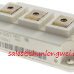
The Infineon BSM200GB120DLC is an IGBT module rated at 1200 V and 200 A, with the continuous-current rating specified at a case temperature of 80 °C. Incoming inspection should preserve those test conditions in the acceptance record rather than treating a cold resistance check as proof of loaded performance.
| Parameter | Official Specification |
|---|---|
| Collector-emitter voltage, VCES | 1200 V |
| Continuous collector current, IC | 200 A at TC = 80 °C |
| Repetitive peak collector current, ICRM | 400 A |
| Gate-emitter threshold voltage, VGE(th) | 5.8 V typical |
| Junction-to-case thermal resistance, per IGBT | 0.24 K/W maximum |
| Operating junction temperature | −40 to +150 °C |
| Isolation voltage | 2500 V AC for 1 minute |
Benchtop Waveform Tuning: Mitigating Stress via Main Terminal Pinout Mechanical Alignment on BSM200GB120DLC
Seat the busbar against each terminal without using the terminal screws to pull misaligned conductors into position. As a Design Consideration, check screw engagement against the approved assembly drawing, including conductor and washer thickness. A bottomed screw can register tightening torque without establishing the intended clamping force; an excessively stiff busbar can transmit assembly loads into the terminal structure.
Compare terminal identification with the circuit diagram before assigning collector, emitter, or gate connections. For diode-mode inspection, hold the gate safely at emitter potential using the approved ESD procedure and record meter polarity, instrument type, and component temperature. A low-current meter reading is a comparative screening result, not a measurement of rated-current conduction loss.
💡 Bench Tip: Use ESD-controlled handling and compare cold readings with a known-good module before interpreting an unusual diode-mode result as a device fault.
For replacement assessment, FZ1600R12KL4C requires a separate electrical, terminal-layout, package, and gate-drive comparison; it should not be treated as a verified direct replacement for this module.
BSM200GB120DLC Operational Boundaries: Evaluating Symmetrical Busbar Geometry for High-Current Paths
Match conductor geometry and gate-return routing when evaluating parallel current paths. As a Design Consideration, symmetrical power connections reduce differences in parasitic impedance, while comparable gate loops help limit unequal switching behavior. Do not assume that a positive temperature coefficient provides current balancing across every operating point; that assessment requires the relevant conduction curves and operating conditions.
The 5.8 V typical threshold identifies the onset of conduction under the specified threshold test, not a recommended gate-drive voltage. Evaluate gate ringing and collector-emitter overshoot with suitable probes, adjusting damping through the system validation process rather than assigning an arbitrary resistor value.
For compatibility assessment in a heavy-duty variable-frequency AC motor drive, review the upstream rectifier, DC-link ripple, and inverter switching conditions separately. Phase-angle control belongs to the appropriate controlled front end, not automatically to this module. RC snubber selection should follow measured transient behavior and loss evaluation. A related device such as BSM100GB120DLC needs its own rating review before consideration in an auxiliary switching stage.
BSM200GB120DLC Thermal-Electrical Optimization: Baseplate Convexity Inspection Practical Tuning
Inspect the mounting surface for contamination, damage, and departure from the specified profile before applying thermal interface material. As an Engineering Recommendation, distinguish an intentional baseplate profile from deformation using the mechanical drawing; do not grind or forcibly flatten the module to match an assumed geometry.
Use the approved interface material and mounting procedure, tightening progressively in the specified cross-pattern. Interface thickness and torque belong to that assembly specification, not to a universal workshop value. The 0.24 K/W maximum junction-to-case resistance per IGBT excludes the additional thermal path through the interface and heatsink.
For pulsed operation, evaluate transient thermal impedance against the actual loss waveform rather than applying steady-state resistance alone. The 400 A repetitive peak rating is not an unrestricted surge-current allowance. The Infineon IGBT Modules Overview provides manufacturer context; the Infineon reverse-conducting IGBT application note concerns a distinct technology and does not establish this module’s internal construction.
BSM200GB120DLC Thermal-Electrical Optimization: Mitigating Bolted Contact Oxidation
Measure bolted-joint resistance with a four-wire micro-ohmmeter, positioning the sense leads across the joint rather than across an arbitrary conductor length. As a Design Consideration, compare equivalent joints at similar temperatures and document lead placement; acceptance limits should come from the equipment’s connection specification.
After controlled energization, compare terminal thermal images under matched loading and surface-emissivity conditions. An elevated terminal temperature warrants checking contact condition, clamping, conductor loading, and measurement setup rather than attributing it immediately to semiconductor damage.
Keep insulation assessment separate: the 2500 V AC, 1-minute isolation specification is a defined withstand rating, not permission to apply that voltage across gate terminals or connected controls. For switching-related preventive checks, Unlocking Efficiency in Industrial Drives offers broader technology context, without identifying BSM200GB120DLC as an IGBT7 device.