
Content last revised on October 3, 2026
CM150DY-34A Circuit Protection and Reliability: Calibrating Galvanic Gate Drive Isolation
| Manufacturer | Mitsubishi Electric |
|---|---|
| Model | CM150DY-34A |
| Product Category | IGBT Module |
| Rated Voltage | 1700 V Official Datasheet Specification |
| Rated Current | 150 A Official Datasheet Specification |
| Package | Module |
Measure the gate to emitter impedance with the power stage fully isolated, then compare the reading with an unused reference unit and the original gate driver board before applying control power. A significant difference between corresponding channels can justify further checks around the gate resistor network, driver output stage, auxiliary emitter path, and insulation surfaces.
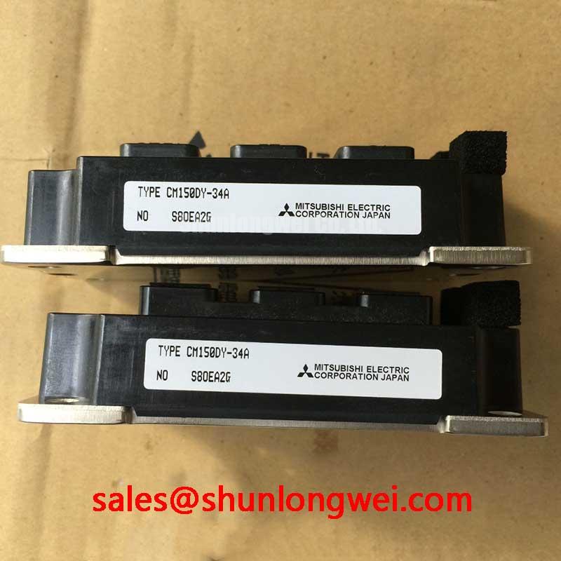
The CM150DY-34A is a Mitsubishi Electric IGBT Module rated at 1700 V and 150 A, with a module package. Those ratings identify the semiconductor’s stated voltage and current class; they do not by themselves define the isolation rating, common mode transient immunity, switching frequency, short circuit withstand time, or complete gate drive requirements. The system engineer should obtain those values from the applicable device documentation and the converter design file.
For a wind turbine full scale converter, the gate drive isolation barrier must be evaluated as part of the complete switching leg. Check the physical separation between primary and secondary control areas, inspect contamination around the isolation barrier, and verify that the isolated power supply remains stable during rapid collector voltage transitions. A digital isolator or optocoupler used in the driver should be selected and tested for the required common mode transient performance; the module itself should not be presented as independently certified for EMC or isolation performance.
When probing a suspected false turn on, use a differential probe across gate and emitter rather than referencing the oscilloscope ground to a high voltage switching node. Capture the command signal, isolated driver output, gate to emitter voltage, and collector emitter response on the same time base. A short unwanted gate pulse may result from driver propagation, common emitter inductance, capacitive coupling, or a control logic fault, so the waveform should be compared against a known good phase rather than assigned to one cause without measurement.
Keep the gate loop compact and route the gate return separately from high current power paths wherever the module layout provides an auxiliary emitter connection. The purpose is to reduce shared inductance and prevent collector current transitions from lifting the local emitter reference. Clearance and creepage are system layout decisions governed by working voltage, pollution environment, insulation system, and applicable standards. Verify them against the complete converter construction rather than treating a generic spacing value as a product guarantee.
For a neutral topology comparison, engineers assessing a related Mitsubishi Electric power module can review CM150DU-34KA. It should be treated as a separate device requiring its own electrical, mechanical, and thermal compatibility checks, not as an automatic substitute.
CM150DY-34A Operational Boundaries: Evaluating Fault Clearing Dynamics
Connect the desaturation or overcurrent diagnostic probe at the driver board and confirm whether the protection signal changes before the gate command is removed during a controlled fault test. Record the gate voltage, driver supply, fault feedback, and collector emitter waveform together so that detection delay, blanking behavior, and turn off behavior can be separated.
Desaturation protection is implemented by the gate driver and its sensing network, not by the bare module alone. Type I or Type II fault handling, blanking time, soft turn off, latch behavior, and restart permission must therefore be verified from the actual driver circuit. Do not assign a universal short circuit response time to the CM150DY-34A without the specific Mitsubishi Electric test conditions and the selected protection circuit.
A two stage turn off strategy may be considered where the converter’s fault energy and stray inductance make an abrupt gate transition unsuitable. The first action limits current through controlled gate discharge, while the final action removes the drive and holds the device in a safe off state. The correct timing and gate current are system determined. During testing, verify that the collector emitter overshoot remains within the voltage boundary of the 1700 V rated device under the worst credible DC link and fault conditions.
Gate resistor selection is also a system tuning task. A resistor that is too small can increase ringing and electromagnetic coupling, while excessive resistance can slow switching and increase switching loss. Start from the original driver design where available, then use an isolated differential probe to observe gate ringing at the actual module terminals. Any change should be checked at the intended temperature, current, DC link condition, and gate driver supply because a bench waveform at low power may not represent converter operation.
The commutation loop should be reviewed at the same time as the protection circuit. Minimize unnecessary conductor length, avoid routing the desaturation sense path beside the collector switching path, and verify the driver’s fault return path. During a regenerative braking event, the chopper and braking resistor absorb energy at the system level; the IGBT module’s voltage stress depends on the DC link control, braking resistor network, switching timing, and parasitic inductance. A compatible upstream rectifier or auxiliary topology may include CM30TF-12E, but its ratings and function must be evaluated independently.
For topology background, the operating principles of a buck converter and zero voltage switching resonant converter are useful when separating hard switching behavior from soft switching behavior. These references describe general power conversion principles and do not establish operating limits for this Mitsubishi Electric module.
CM150DY-34A Transient Dynamics and Electrical Design: Baseplate Contact and Screw Installation
Inspect the module mounting surface for burrs, contamination, uneven contact marks, and distortion before measuring the thermal interface condition. A poor mechanical interface can cause localized heating even when the electrical waveform appears normal, so compare the baseplate contact pattern with the heatsink surface and inspect the fasteners for uneven seating.
The CM150DY-34A uses a module package, but the available core specification does not establish a universal heatsink flatness value, thermal interface thickness, or mounting torque. These details must come from the applicable mechanical drawing and the selected fastener specification. The interface material should be applied as a uniform, controlled layer without trapped air, while the heatsink surface should be clean and free from particles that can tilt the baseplate.
When the baseplate appears convex or the heatsink has a matching machining error, do not attempt to compensate by excessive fastener force. Recheck the mechanical parts, mounting sequence, and contact surfaces. Tighten progressively in a balanced sequence so that the module seats evenly. The final torque is a Design Consideration determined by the module drawing, screw size, washer arrangement, thread condition, and heatsink material.
Thermal verification should include the transient thermal impedance network used by the converter model. A short braking pulse and a sustained current interval produce different junction temperature responses, so average case temperature alone is not enough for evaluating pulse operation. Designers should correlate the calculated junction temperature with thermocouple or infrared measurements taken under controlled switching conditions, while accounting for sensor placement and emissivity limitations.
Check the power terminal busbars for mechanical strain after the module is secured. A busbar that pulls on the terminal can transfer stress into the module body or alter the commutation loop. Keep the high current path compact, and place the gate driver connection so that power terminal current does not share the gate return conductor. Where an auxiliary emitter terminal is provided in the applicable configuration, route it as a dedicated control reference and verify the exact terminal assignment from the original device documentation.
Field Alert: Disconnect the DC link and control supplies before inserting or removing gate cables, and follow the specified fastener torque rather than relying on hand tightness.
CM150DY-34A Operational Boundaries: Evaluating Dynamic Gate Impedance Control
Probe the gate to emitter voltage directly at the module terminals during the highest dv/dt switching event, then compare the off state level and any induced pulse with the driver output at the isolation boundary. This measurement distinguishes a genuine control command from a transient coupled into the gate loop.
Cross conduction can involve several interacting paths, including Miller coupling, common emitter inductance, driver output impedance, isolated supply behavior, and timing overlap between complementary devices. An active Miller clamp may be evaluated when the selected gate driver supports it, but its clamp current capability and connection must match the module terminal arrangement. The system integrator should confirm that the clamp engages only after the intended turn off sequence and does not interfere with controlled fault turn off.
Negative gate bias is not a universal requirement that can be assigned to every installation of the CM150DY-34A. If the original converter uses a negative off state, reproduce the documented value and verify the module’s permitted gate emitter voltage range from the applicable Mitsubishi Electric data. If it does not, do not introduce negative bias as a corrective measure without checking driver supply isolation, gate oxide stress limits, turn off transients, and the complete protection scheme.
Gate loop impedance should be controlled through short conductors, a defined return path, and suitable damping selected by waveform testing. Examine the rising and falling edges at the module terminals, not only at the driver connector. Ringing that is absent at the driver but visible at the module indicates a layout or interconnect issue that may require revised routing, local damping, or a different driver interface.
For converters used in potential onshore or offshore wind turbine applications, switching tests should include normal motoring, regenerative operation, braking transitions, startup, shutdown, and fault recovery. Verify peak voltage, gate excursion, current sharing, thermal response, and protection timing at the system operating points. The module’s official identity remains 1700 V, 150 A, Mitsubishi Electric, module package; safe converter performance depends on the complete electrical, thermal, mechanical, and control implementation.
Engineers reviewing high speed silicon carbide alternatives or mixed technology architectures may consult The 1200 V CoolSiC™ MOSFET Advantage in Three as a separate technical reference. Device substitution still requires a new gate drive, protection, thermal, switching loss, and insulation assessment.