Content last revised on September 10, 2026
Atmospheric Neutron Radiation Impact on 1200V/1700V Silicon Reliability
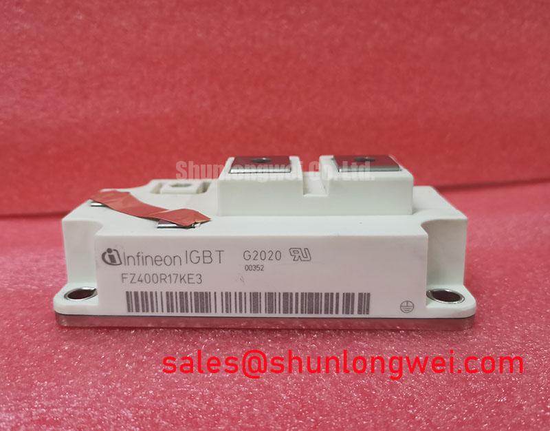
Operating multi-megawatt wind turbine full-scale converters in elevated onshore plateaus or offshore installations places extreme electrical stress on power stages. The FZ400R17KE3_S4 single-switch module is rated for a continuous collector current of 400A at a case temperature of 80°C and a collector-emitter blocking voltage of 1700V (Official Datasheet Specification). In high-altitude environments exceeding 2000 meters, terrestrial cosmic neutron flux increases sharply, presenting a genuine mechanism for Single Event Burnout (SEB).
When high-energy atmospheric neutrons strike the high-electric-field drift region of the silicon die while blocking DC-bus voltages, they generate localized charge carrier cascades via impact ionization. If the localized electric field gradient surpasses critical thresholds, it triggers unrecoverable avalanche breakdown, culminating in instantaneous collector-to-emitter short-circuits without prior thermal warning. To maintain acceptable FIT (Failures in Time) rates in turbine nacelles, a DC-link operating voltage derating to between 900V and 1100V is an essential Design Consideration. For comprehensive insulation diagnostic methods and field test procedures on degraded blocking junctions, refer to the Field Engineer’s Handbook.
Thermal Paste Degradation Prevention and Mechanical Clamping Torque Calibration
Thermal management in variable-speed wind conversion demands strict control over baseplate mechanical assembly to maintain the specified thermal resistance junction-to-case of RthJC = 0.040 K/W per IGBT (Official Datasheet Specification). Over repetitive generator gust loading cycles spanning the operating junction temperature range of -40°C to +125°C, thermal paste pump-out and dry-out represent leading causes of module overheating.
Applying thermal interface material (TIM) requires a uniform thickness of 50 µm to 100 µm, ideally achieved via screen printing to prevent void formation beneath the silicon substrate. Baseplate clamping must follow a calibrated sequential cross-pattern: snug all M6 mounting bolts finger-tight, pre-torque to 2.0 N·m, and perform final fastening between 3.0 N·m and 6.0 N·m (Design Consideration based on standard module baseplate mechanics). Proper terminal tightening prevents mechanical micro-fretting on main current paths.
⚠️ Field Alert: Never reuse dried thermal interface compound or overtighten corner mounting bolts without a calibrated torque wrench. Excessive torque causes convex baseplate bowing, lifting the central substrate away from the heatsink surface and inducing localized thermal runaway within minutes of converter energization.
When servicing modular wind converters requiring alternative current ratings or standard 1200V platform designs, engineering teams often evaluate the related FZ600R12KE4 as an option for lower-voltage multi-parallel sub-assemblies.
High-Frequency Commutation Loop Inductance Minimization in High-Power Arrays
In multi-megawatt generator inverter legs, rapid switching transients generate significant inductive overvoltage across the module terminals. During turn-off, parasitic loop inductance induces a transient voltage peak determined by the DC-link voltage combined with the product of stray inductance and the turn-off di/dt rate. With the FZ400R17KE3_S4 switching hundreds of amperes, unmitigated busbar inductance can push collector-emitter voltages beyond the 1700V absolute rating.
To restrict commutation loop stray inductance below 25 nH, technicians must verify symmetrical, planar laminated DC busbar structures with low-inductance snubber film capacitors mounted directly across the module collector and emitter terminals. Gate loop wiring must use tightly twisted pairs positioned orthogonally to the high-current AC output paths to prevent inductive noise injection onto the gate-emitter junction. For converter topologies requiring dual-switch half-bridge structures with integrated temperature sensors, engineers can review the complementary FF650R17IE4DP_B2 module layout.
High-Speed Fault Management: VCE(sat) Desaturation Sensing Circuitry
Short-circuit protection in grid-tied wind converters relies on rapid desaturation sensing. Under normal operating conditions, the module exhibits a typical on-state saturation voltage of VCE(sat) = 2.00V at 400A with a typical gate threshold voltage of VGE(th) = 5.8V (Official Datasheet Specifications). During a Type-I or Type-II short-circuit fault, the collector voltage exits saturation rapidly, rising toward the full DC-bus potential while carrying extreme fault currents.
Gate driver desaturation detection must recognize this condition and trigger a safe shutdown within the standard Short-Circuit Safe Operating Area (SCSOA) window of under 10 µs. A hard gate discharge during high-current desaturation generates destructive di/dt overvoltage. Therefore, gate driver circuitry must implement a two-stage soft turn-off (STO) sequence, gently ramping down the gate voltage to discharge the gate charge safely without exceeding the 1700V breakdown threshold.
Field Diagnostic Verification Steps
- Collector-Emitter Cold Check: Using a digital multimeter in diode mode, verify forward voltage across the antiparallel freewheeling diode (typically 0.3V to 0.7V depending on ambient temperature) and verify infinite reverse resistance.
- Gate-Emitter Integrity Check: Confirm infinite resistance (high-megaohm range) between the gate and auxiliary emitter terminals; any reading below 1 MΩ indicates internal gate oxide breakdown.
- Desaturation Diode Check: Measure the high-voltage blocking diode in the driver desaturation sensing path to ensure it has not failed shorted, which would feed high DC-link potential directly into the driver logic stage.