
Content last revised on September 10, 2026
CM50DU-24H Dual IGBT Module: Precision Power Switching for Industrial Systems
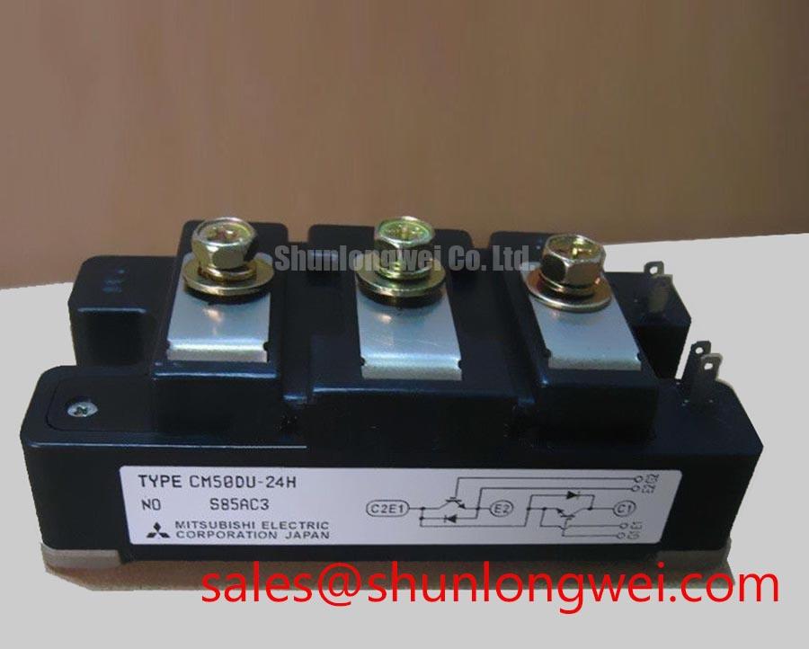
The CM50DU-24H by Mitsubishi is a high-reliability dual IGBT module designed for medium-power switching applications. Featuring a half-bridge topology, this module delivers robust thermal management and low conduction losses to maximize system efficiency. With a rating of 1200V and 50A, it provides the voltage headroom needed to operate safely on 480VAC industrial mains. Two key design advantages of this module include simplified half-bridge layout routing and a highly isolated copper baseplate. For 1200V motor drives prioritizing low thermal resistance, the 50A CM50DU-24H provides an optimal performance-to-footprint ratio.
Key Parameter Overview
Decoding the Specs for Enhanced Thermal Reliability
Understanding the electrical and thermal boundaries of the CM50DU-24H is crucial for ensuring long-term system reliability. The table below outlines its critical maximum ratings and electrical characteristics, along with their engineering value.
| Parameter | Symbol | Official Specification | Value & Engineering Interpretation |
|---|---|---|---|
| Collector-Emitter Voltage | VCES | 1200V | Provides excellent voltage derating headroom in standard 480VAC industrial systems. |
| Continuous Collector Current | IC | 50A (at Tc = 25°C) | Suited for mid-range power conversion and motor control circuits. |
| Peak Collector Current | ICM | 100A | Accommodates startup surge currents without triggering desaturation protection. |
| Maximum Collector Dissipation | Pc | 400W (at Tc = 25°C, Tj ≤ 150°C) | Defines the absolute power dissipation limit under optimal cooling conditions. |
| Collector-Emitter Saturation Voltage | VCE(sat) | 2.9V (Typical) / 3.7V (Max) | Determines steady-state conduction losses during high-current operation. |
| Thermal Resistance (Junction to Case) | Rth(j-c)Q | 0.31 K/W (per IGBT) | Indicates the efficiency of heat transfer from the silicon junction to the package baseplate. |
| Isolation Voltage | Viso | 2500 Vrms (AC 1 minute) | Ensures safe electrical isolation between the power terminals and the heatsink. |
Download the CM50DU-24H datasheet for detailed specifications and performance curves.
Application Scenarios & Value
Achieving System-Level Benefits in High-Frequency Power Conversion
Engineers often face the challenge of startup surge currents in motor drive applications, where transient thermal loads can damage standard switching components. The CM50DU-24H resolves this with its high peak collector current of 100A and low junction-to-case thermal resistance of 0.31 K/W, ensuring the module stays within safe operating parameters during short-duration overloads. The half-bridge configuration makes it highly suitable for variable frequency drives (VFDs), AC/DC motor controllers, uninterruptible power supplies (UPS), and induction heating systems.
By integrating the free-wheel diode directly into the copack layout, designers can achieve tight loop routing that adheres to strict IEC 61800-3 electromagnetic compatibility standards. While this 50A module is ideal for medium-power applications, systems requiring higher current handling can look to the related CM100DY-24H which offers a 100A rating, or the CM200DY-24H for 200A current handling.
Technical Deep Dive
A Closer Look at the Dual-Gate Structure and Thermal Dissipation
The internal architecture of the CM50DU-24H utilizes Mitsubishi's mature chip technology, combining two IGBT switches with reverse-connected super-fast recovery free-wheel diodes. This dual configuration optimizes loop design by reducing parasitic inductance. What is the primary benefit of the isolated copper baseplate? It facilitates direct heatsink mounting to optimize heat dissipation. How does the dual configuration benefit layout design? It minimizes parasitic loop inductance by simplifying half-bridge wiring.
To understand the thermal pathways, consider that the thermal resistance Rth(j-c)Q of 0.31 K/W acts like a multi-lane thermal highway. Heat generated in the silicon junction transitions swiftly to the copper baseplate and heatsink without bottlenecking, protecting the silicon from thermal runaway. Additionally, the gate charge QG of 187 nC acts like a small reservoir. Because the gate requires relatively little charge to reach full saturation, the gate driver can turn the switch on and off rapidly—similar to a quick-release valve—minimizing the time spent in the high-loss linear switching region. Utilizing a proper in-depth analysis of IGBT modules can help optimize driver selection to match these gate charge characteristics. Proper implementation also helps prevent gate oxide stress, which is a key focus of IGBT failure analysis in long-lifecycle designs. Engineers should also verify the Short-Circuit Withstand Time ratings to design robust overcurrent protection circuits.
Frequently Asked Questions
Addressing Critical Integration and Design Queries
- How does the thermal resistance Rth(j-c)Q of 0.31 K/W affect heatsink selection for the CM50DU-24H?
A lower junction-to-case thermal resistance means less temperature rise for a given power dissipation. With Rth(j-c)Q at 0.31 K/W, the thermal path is highly efficient, allowing designers to specify smaller, lighter heatsinks or operate the system with a higher thermal safety margin. - Is the 1200V rating sufficient for 480VAC industrial applications?
Yes. In standard 480VAC three-phase systems, the DC bus voltage typically hovers around 650V to 680V. The 1200V maximum collector-emitter voltage (VCES) provides a robust safety margin to handle transient overvoltages and inductive switching spikes. - How does the gate charge QG of 187 nC influence gate driver requirements?
The gate charge determines the driver current required to switch the module at a target frequency. Because 187 nC is relatively low, it reduces the driver power consumption and allows the use of more compact, cost-effective gate drivers while maintaining fast switching speeds. - Why is the 2500 Vrms isolation voltage rating significant?
The 2500 Vrms isolation rating ensures that the internal electrical components are safely isolated from the metal baseplate. This complies with international safety standards and allows the module to be bolted directly to a grounded heatsink without additional insulating pads. - What precautions should be taken regarding the mounting torque specs?
The mounting terminals must be tightened within 2.5 to 3.5 N·m for M5 main terminals, and 3.5 to 4.5 N·m for the M6 mounting screws. Over-tightening can crack the ceramic substrate inside the module, while under-tightening increases electrical and thermal contact resistance.