Content last revised on October 30, 2026
Transient Dynamics & Electrical Design: Pollution Degree 3 Creepage Distances on CM600HA-24E
With the DC link discharged and the gate driver disconnected, identify the collector, emitter, and gate markings on the CM600HA-24E before taking any resistance or diode-mode readings. Record the instrument polarity and module temperature so subsequent measurements can be compared under the same conditions. A reading taken through an attached driver, snubber, or busbar network is not an isolated module measurement.
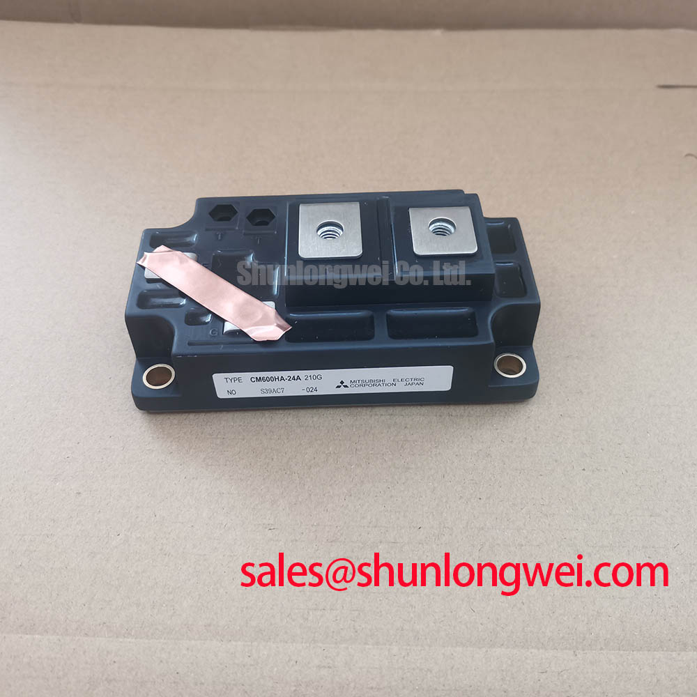
The Mitsubishi Electric CM600HA-24E IGBT module has official specifications of 1200 V collector-emitter voltage, 600 A continuous collector current at a case temperature of 25°C, and 2.1 V typical collector-emitter saturation voltage under the datasheet test conditions. The saturation-voltage figure is a datasheet operating-point characteristic, not a multimeter acceptance threshold. For incoming inspection, separate identification checks, cold electrical screening, and powered characterization rather than treating them as interchangeable tests.
Inspect the insulating surfaces between power terminals and the baseplate for conductive residue, moisture tracks, and mounting debris before connecting an insulation tester. As a Design Consideration, contamination can change the external leakage path even when the semiconductor terminals show no obvious cold-test abnormality. Document the location of deposits before cleaning so an enclosure or installation problem is not mistaken for an isolated component fault.
The official isolation specification is 2500 Vrms between the power terminals and baseplate. This is an AC withstand rating, not an insulation-resistance limit or a continuous working-voltage declaration. It does not establish a DC insulation-test voltage or a megohm acceptance threshold. Select the inspection procedure from the applicable manufacturer test instructions, including terminal grouping, waveform, duration, and equipment disconnection requirements.
For a Pollution Degree 3 installation, the Design Consideration is to evaluate external creepage and clearance within the complete assembly. IEC 60664-1 provides the insulation-coordination framework; the required distances depend on working voltage, material group, overvoltage conditions, and the installation environment. Measure the actual paths around terminal barriers and mounting hardware rather than assigning a universal spacing to this module. An isolation rating alone does not establish suitability for that pollution degree.
An insulation result should also be interpreted within the test arrangement. Surface leakage, connected circuitry, and fixture contamination can influence the measurement; terminal-to-baseplate testing cannot, by itself, identify a particular internal material or locate a defect. 💡 Bench Tip: Use ESD precautions and compare cold readings with a known-good reference under matching conditions before proceeding to any approved high-voltage test.
Field Diagnostics & Commissioning: High-Speed Semiconductor Fuse I²t Melting in CM600HA-24E Topologies
Compare the semiconductor fuse’s total clearing characteristics with the prospective fault current and DC-link conditions, rather than selecting it from the module’s 600 A rating alone. As a Design Consideration, pre-arcing I²t describes only part of the interruption event; the arcing interval and recovery voltage also matter. Use fuse data applicable to the actual DC voltage and circuit time constant when assessing coordination.
A fuse and an electronic gate-protection circuit perform different jobs. The driver should detect and respond to abnormal switching conditions within the module’s applicable protection limits, while the fuse interrupts the fault path according to its operating characteristics. Neither a generic fuse I²t comparison nor the collector-current rating establishes a guarantee against enclosure damage. Coordination requires the relevant semiconductor withstand information and system-level fault assessment.
During commissioning, examine the protection sequence from fault detection through gate discharge and DC interruption. As an Engineering Recommendation, record whether the driver supply remains valid while the protection circuit operates. A collapsing supply can alter gate control precisely when the circuit needs a predictable response. Check undervoltage lockout behavior and fault-reset sequencing against the driver documentation, with test energy controlled by the equipment’s approved procedure.
If the high-side driver uses a bootstrap supply, its charge budget should cover gate charge, driver quiescent consumption, and leakage throughout the longest interval without recharge. This is a Design Consideration, not a fixed capacitor prescription for the CM600HA-24E. Account for effective capacitance under bias, permissible supply droop, and the available recharge interval. Operating sequences with prolonged high-side conduction deserve particular attention because the recharge opportunity is determined by the topology and modulation.
For auxiliary-stage assessment, CM50MX-24A is a separate component reference, not evidence of a compatible rectifier stage or an interchangeable power switch. Its circuit role should be established from its own terminal diagram and ratings before it enters the same protection review.
Field Diagnostics & Commissioning: Gate Drive Resistance Calibration During Replacement in CM600HA-24E Topologies
Capture gate-emitter voltage at the module terminals when evaluating an existing driver board, because a clean waveform at the driver output can conceal ringing along the interconnect. As a Design Consideration, probe reference placement and measurement-loop area affect the observed transient. Compare turn-on and turn-off behavior separately, using a measurement arrangement suitable for the switching-node common-mode voltage.
External turn-on and turn-off resistance influence switching speed, loss, overshoot, and susceptibility to unintended gate movement. Treat resistor changes as controlled calibration rather than an automatic improvement: slower switching can reduce some transient stress while increasing switching dissipation. Select the final values from the module’s switching characteristics, driver capability, and measured behavior across the intended operating envelope.
A replacement assessment should distinguish an identified candidate from a demonstrated electrical and mechanical match. The comparison below preserves that distinction without assigning unsupported ratings to another part.
| Assessment item | CM600HA-24E | MPKB2SA100U60 |
|---|---|---|
| Manufacturer | Mitsubishi Electric | Consult datasheet |
| Collector-emitter rating | 1200 V, Official Specification | Consult datasheet |
| Continuous collector current | 600 A at case temperature 25°C, Official Specification | Consult datasheet |
| Typical saturation voltage | 2.1 V under datasheet test conditions, Official Specification | Consult datasheet and test conditions |
| Replacement qualification | Original reference for this assessment | Direct interchangeability not established |
The MPKB2SA100U60 should therefore remain a comparison candidate until its topology, terminal arrangement, mounting interface, gate requirements, and thermal limits have been matched. As an Engineering Recommendation, preserve separate records for dimensional compatibility and switching compatibility; fitting the busbars does not demonstrate acceptable operation on the existing driver.
Also evaluate the optocoupler or digital isolator’s common-mode transient immunity against the measured switching environment. Confirm that dead time prevents overlap throughout propagation-delay variation without prescribing a universal timing value. Mitsubishi Electric’s SiC Power Modules & SBDs resource provides context for a different device technology; its characteristics should not be transferred to this IGBT module.
CM600HA-24E Thermal-Electrical Optimization: Static and Dynamic Current Distribution and Practical Tuning
Compare voltage drop and temperature under controlled load before attributing unequal branch current to gate resistance. The official CM600HA-24E thermal specification is 0.052 K/W maximum junction-to-case thermal resistance, with an official operating junction-temperature range of −40 to +150°C. Junction-to-case resistance excludes the interface material, heatsink, and coolant or ambient path.
For parallel operation, a Design Consideration is that a positive saturation-voltage temperature coefficient can assist static sharing only within the operating region where the device characteristics demonstrate that behavior. Do not assume it across the entire current range. Compare the relevant temperature-dependent curves and measured branch drops; balanced cooling and similar connection resistance remain important even where the coefficient is favorable.
Dynamic sharing requires attention to gate-loop symmetry, power-path impedance, and driver timing. Compare branch waveforms during switching rather than relying only on averaged current. Mechanical integration should provide consistent baseplate contact without using mounting pressure to compensate for an unsuitable mating surface. The discussion in The Advanced Thermal Management Revolution offers broader thermal-management context, not confirmation of this module’s internal construction.
When assessing compatibility with a utility-scale centralized battery energy storage PCS, designers should examine both charging and discharging thermal cycles, including operating transitions that change semiconductor loss distribution. As an Engineering Recommendation, correlate case-temperature measurements with the validated thermal model and operating waveform. Adjust cooling, current scheduling, or switching conditions according to the resulting junction-temperature assessment rather than assigning a service-life claim from the temperature rating alone.