


Content last revised on October 6, 2026
CM75DU-12H Thermal-Electrical Optimization: Mitigating Hard Switching Transients via Practical Tuning
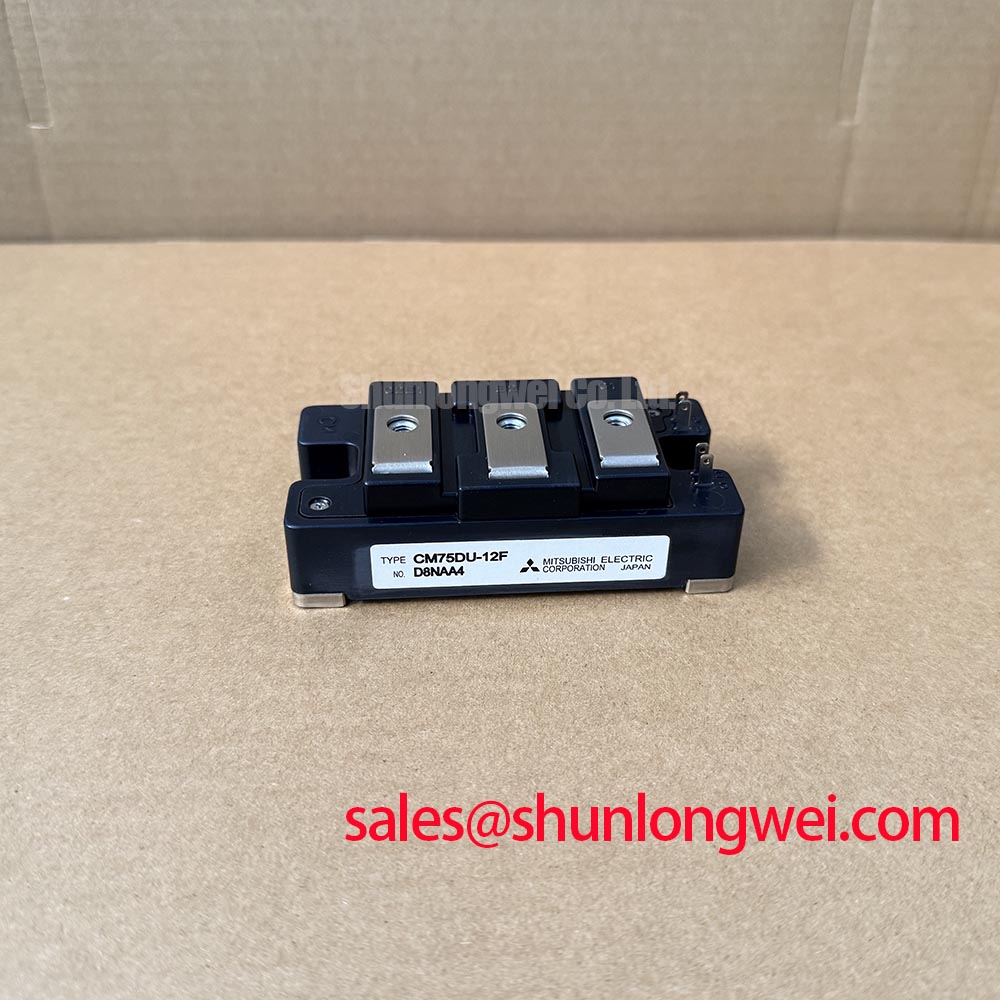
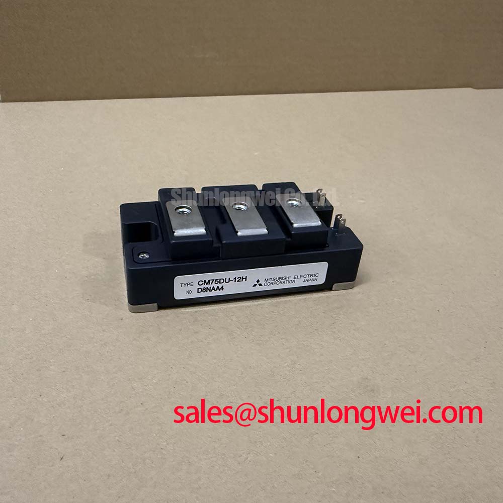
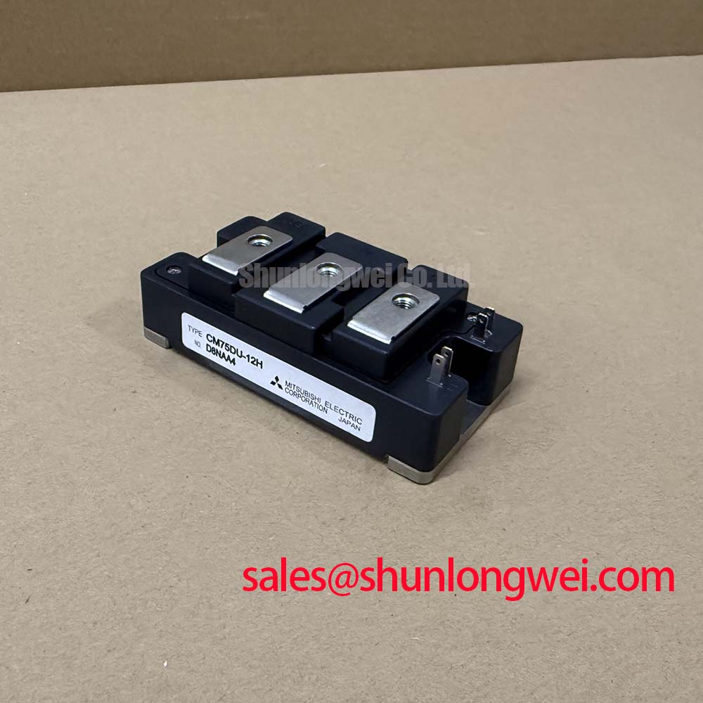
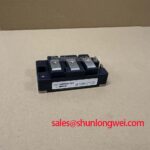
With the DC link discharged and isolated, check the removed module’s cold terminal readings against the service record before fitting a CM75DU-12H. Mitsubishi Electric rates this IGBT module at 600 V and 75 A (Official Specification). Those ratings identify an electrical boundary, not a complete replacement decision: terminal layout, mounting, gate-drive connections and operating conditions still need to match the original equipment documentation.
After a switching-related shutdown, inspect the module terminals, bus connections and gate wiring before attributing the fault to the semiconductor. A loose power connection can change loop impedance; an altered gate path can change switching behavior. Record cold readings with the module disconnected, then compare them with a known-good assembly or the equipment’s service data. A handheld meter is an initial screen, not a test of switching performance.
Design Consideration: Keep the DC-link switching loop compact to limit inductive voltage overshoot during turn-off. On a controlled test bench, observe collector-emitter voltage and gate-emitter voltage together under the intended load. Protection logic should distinguish short-circuit events from ordinary switching transients; its detection interval and any staged, softer turn-off must be validated against the module’s documented safe-operating limits and the actual driver. No short-circuit withstand time or prescribed turn-off profile is established by the ratings above.
Thermal contact is part of the same assessment. Check the mounting surface for damage, apply the interface material in accordance with the assembly procedure, and compare temperature behavior after repair with the machine’s established baseline. ⚠️ Field Alert: Do not loosen or refit module terminals until the DC link has been isolated and its discharge verified. For background on heat-flow choices rather than a claimed construction detail of this module, see The Advanced Thermal Management Revolution.
CM75DU-12H Thermal-Electrical Optimization: Isolated DC-DC Power Supply Sizing for High Practical Tuning
A replacement module cannot correct a gate supply that collapses during a switching event. At the driver, measure the gate supply while commanding transitions and compare its response with the equipment design. Inspect the return path and external gate resistor for changed connections or heat damage. Design Consideration: Size the isolated supply and its sourcing and sinking capability from the documented gate-drive requirements, switching duty and measured gate waveform, rather than from the module’s 75 A current rating alone.
Gate-loop inductance and common-mode movement can appear as ringing or an unintended gate pulse. Keep the drive and return paths closely coupled, then assess external gate-resistor damping on the bench while checking both switching loss and voltage overshoot. A negative off-state bias, where the original driver uses one, requires verification against its driver and module limits; it is not a value to infer from this product’s voltage rating.
Design Consideration: Verify the gate supply’s isolation and transient-immunity requirements from the complete equipment design and the supply manufacturer’s documentation. The stated 600 V module rating does not establish a reinforced-isolation rating for an external DC-DC converter. Documentation for an adjacent operator display, including the Innolux Corporation industrial display portfolio, likewise cannot qualify the power stage’s isolation barrier.
Assembly Integrity & Layout Architecture: Implementing Output Sinusoidal Filter vs dv/dt Reactor for CM75DU-12H
Trace the output cable before changing a filter. In a motor-drive assembly, cable length and termination can produce reflected-wave voltage at the load; the measured peak depends on the cable, load and switching edge. Capture the waveform at the relevant terminals and compare it with the equipment limits. A sinusoidal output filter and a dv/dt reactor address different waveform requirements, so their selection belongs to the system design, not to the CM75DU-12H part number.
For an industrial inverter welder or medium-frequency induction-heating supply, first verify that the original circuit actually uses the output network under consideration. These are potential compatibility assessments, not stated applications or approvals for the module. If a regenerative path is present, examine its braking chopper and resistor arrangement separately; energy absorption cannot be assigned to the IGBT module by itself.
Design Consideration: Preserve the equipment’s specified terminal spacing and insulation barriers during reassembly. Creepage, clearance and any altitude-related adjustment require the applicable installation standard, enclosure conditions and insulation design. The supplied module ratings do not establish an altitude derating, insulation-reliability claim or cosmic-ray-related failure rate.
Preventing Spurious Faults: Multi-Module Parallel Current Sharing Guidelines for CM75DU-12H
Before investigating parallel sharing, confirm that the equipment schematic calls for parallel modules. Compare each branch’s cold connections, gate-drive path, bus geometry and thermal mounting. During controlled operation, measure branch currents and gate waveforms at comparable points. Unequal current can reflect more than a semiconductor difference, so a single reading should not be treated as a diagnosis.
Design Consideration: Symmetrical power and gate paths help limit dynamic imbalance. A positive temperature coefficient of on-state voltage can assist static sharing under some operating conditions, but it must not be assumed for the CM75DU-12H across the intended current and temperature range without the relevant device data and measurements. If comparing another module such as the CM100DY-12E, check its electrical limits, terminal arrangement, driver requirements and thermal interface independently before considering compatibility.
Where parallel branches trip intermittently, capture current and gate behavior during the event, then inspect connection integrity after shutdown. Leave final protection thresholds and sharing margins to the equipment design and its switching-test results.