Content last revised on October 10, 2026
Transient Dynamics and Electrical Design: Diagnosing Latent Gate Emitter Dielectric on CM900HG-130X
With the inverter isolated and fully discharged, measure the main terminal paths and antiparallel diode with a digital multimeter in diode check mode before applying any control or DC-link voltage. Keep the gate and emitter shorted during the main-terminal checks to prevent accidental turn-on from a charged gate. This cold screening can help identify gross shorts or an abnormal diode response without exposing the replacement assembly to an energized test, but it does not establish gate dielectric integrity or high-voltage blocking capability.
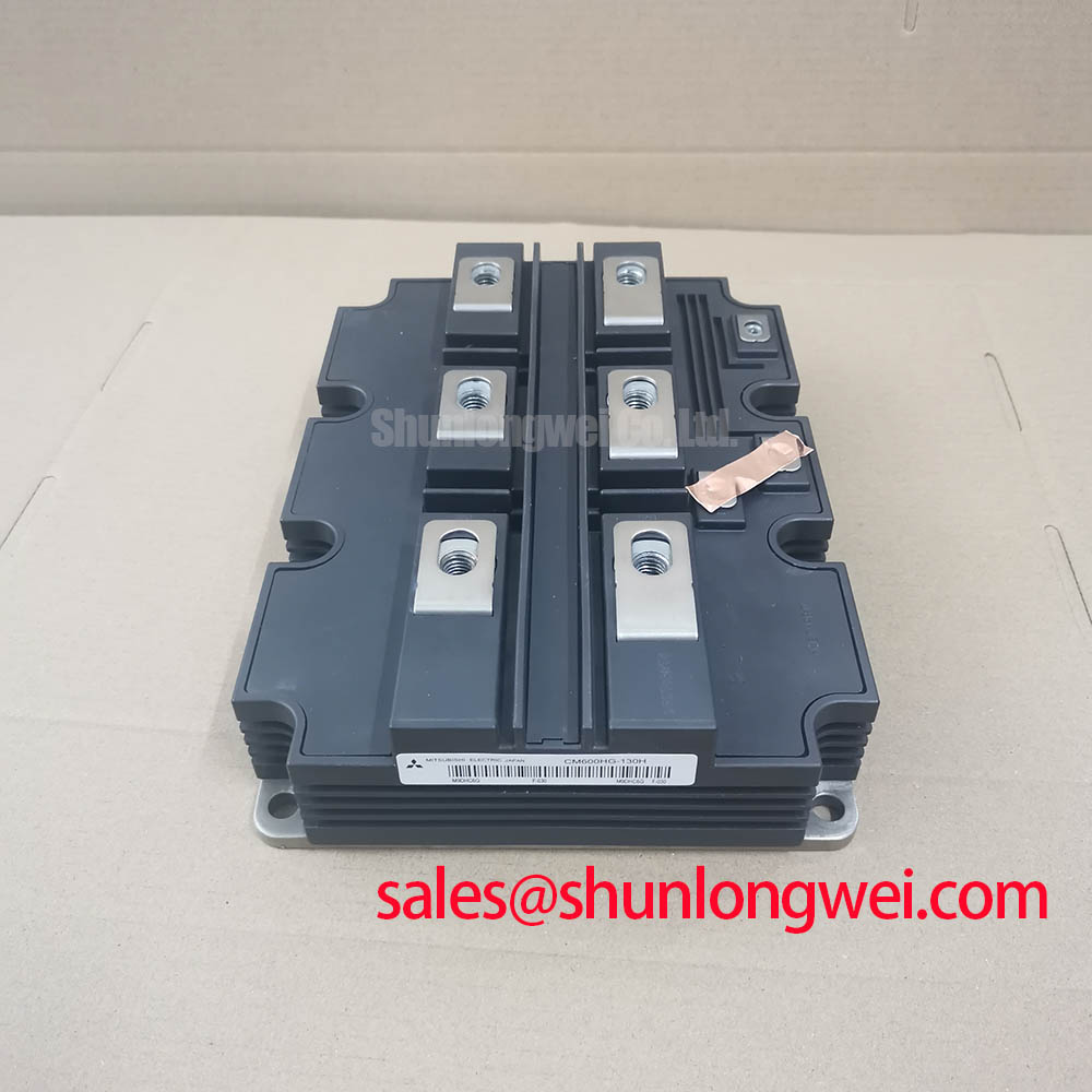
The CM900HG-130X is a Mitsubishi Electric IGBT Module with a specified collector-emitter voltage rating of 6500 V and a rated collector current of 900 A under the datasheet conditions. Its listed package is Module. These values identify the component class and electrical rating; they do not, by themselves, confirm suitability for every switching frequency, thermal arrangement, DC-link topology, or protection circuit.
| Specification | Value | Classification |
|---|---|---|
| Manufacturer | Mitsubishi Electric | Official product identification |
| Model | CM900HG-130X | Official product identification |
| Collector-emitter voltage rating | 6500 V | Datasheet rating |
| Rated collector current | 900 A under the datasheet conditions | Datasheet rating; not an unconditional operating current |
| Package | Module | Official product classification |
Gate integrity should be checked before any high voltage commissioning because a gate oxide or gate emitter insulation problem can remain hidden while the power terminals appear electrically normal. Keep the module unpowered, isolate the module’s gate-emitter connections from the driver circuitry, and compare the gate emitter reading with the known-good reference module or the original maintenance record. Use a test method that stays within the documented gate limits. The purpose is to identify abnormal leakage or an unexpected conductive path, not to assign a failure cause from one meter reading.
During the same cold inspection, test the main semiconductor path and the antiparallel diode in the polarity required by the module’s terminal arrangement. Confirm the physical terminal design from the applicable Mitsubishi Electric documentation before placing probes on high-current connections. A low-resistance result in both polarities, a diode response that differs materially from the paired phase position, or unstable readings after the terminals are cleaned should trigger a controlled isolation test rather than immediate energization.
Gate drive boards used in legacy industrial equipment deserve particular attention. Optocouplers and digital isolators can experience common-mode transients when the power stage switches rapidly. Designers should inspect the isolation barrier layout, return-current path, gate-emitter reference, and clamp network as one system. The required drive voltage, negative bias, dead time, and gate resistance must come from the original drive design and the applicable device documentation rather than from a generic IGBT rule.
For a utility-scale 1500 V central photovoltaic inverter, this module should be evaluated within the complete power-stage and isolation topology. A 6500 V module rating alone does not establish suitability for a 1500 V DC link. The system engineer must establish the voltage distribution, switching-node transients, insulation coordination, and protection response through the inverter’s approved architecture.
The Mitsubishi Electric power semiconductor reference provides useful manufacturer-level context for high-power module families and their application environment. It should be read together with the exact device documentation governing terminal identification, gate limits, thermal conditions, and switching behavior.
Assembly Integrity and Layout Architecture: Implementing Oscilloscope Waveform Verification for CM900HG-130X
When replacing a module on an older drive board, begin with terminal identity and mechanical alignment rather than changing gate resistor values. Mark the collector, emitter, gate, and auxiliary connections from the original wiring record, then confirm that the busbar, gate return, and emitter reference reach the intended terminals without relying on physical position alone.
External RG(on) and RG(off) influence the compromise between switching loss, ringing, control noise, and short-circuit response. A practical engineering recommendation is to retain the legacy resistor arrangement for the first controlled comparison when its electrical rating and isolation condition are acceptable and the arrangement is compatible with the replacement module's documented drive requirements. Adjustments should then be made from oscilloscope evidence, observing gate voltage, collector emitter voltage, current, and the driver supply at the same event.
Use a differential high-voltage probe and a properly rated current probe when reviewing switching waveforms. Probe loop area should be minimized, and the measurement reference should remain consistent between the original and replacement configurations. Gate ringing that appears only after the retrofit may indicate a changed parasitic network, an altered driver load, or an unsuitable gate-return path; it should not be attributed to the module alone without comparing the complete commutation loop.
High-current busbars should remain mechanically supported close to their intended terminals, with contact surfaces clean, flat, and free from excess joint compound. Vibration-proof fastening is a design consideration for industrial cabinets, but the correct fastener grade, washer arrangement, and tightening torque must follow the equipment assembly specification. Creepage and clearance must also be checked around the energized conductors, especially where an older mounting plate was reused after the module footprint changed.
Maintenance Note: Inspect heatsink cleanliness, thermal interface condition, terminal tightness, and contact temperature during scheduled maintenance, with the air path checked for dust accumulation and condensation risk.
Field Diagnostics and Commissioning: Coordinating High-Speed Arcing Voltage in CM900HG-130X Topologies
Fast semiconductor fuse coordination must be evaluated against the module’s short-circuit and transient limits as a complete protection study. Fuse total clearing I2t, prospective fault current, DC-link capacitance, cable inductance, and gate shutdown behavior all affect the energy delivered during a hard fault. Fast gate protection is generally required to limit IGBT short-circuit stress; a fuse alone should not be assumed to clear within the module’s withstand time. Fuse selection must address fault isolation and damage containment, while the protection circuit must also avoid nuisance operation during legitimate switching events.
During commissioning, verify that any fuse monitoring and gate inhibit paths respond as intended by the equipment design. A protection signal that reaches the controller but not the gate driver can leave the power stage exposed, while a driver shutdown without adequate fault isolation may produce repeated restart attempts. Record the fault sequence, gate response, DC-link behavior, and fuse condition using the equipment’s approved measurement procedure.
Pressurized arc interruption and enclosure integrity require system-level assessment. Do not infer case rupture resistance from the module’s current rating. The cabinet, busbar spacing, fuse class, venting strategy, and protective barriers must be considered together under the applicable safety and insulation requirements. No individual IGBT module independently establishes compliance with an industrial equipment certification or EMC standard.
For maintenance teams working on large photovoltaic inverter cabinets, commissioning should include an isolation check of the gate driver, a controlled low-energy switching test, and a review of the fault recorder before full-power operation. The operating envelope must be validated against the approved inverter design, not extended simply because the replacement part carries a high current rating.
The related Industrial Applications guide can support broader discussions of IGBT use in renewable-energy and heavy-industry power conversion. It should complement, not replace, the module-specific electrical and mechanical documentation.
Preventing Spurious Faults: Planar Symmetrical Busbar Geometry Guidelines for CM900HG-130X
Turn-off overshoot is governed by the interaction between DC-link voltage, stray inductance, and switching current rate. In practical terms, inadequate control of the commutation loop’s inductive energy can increase the peak voltage. The engineering calculation follows the relationship between the DC-link term and the inductive voltage contribution, while the final allowable peak must be checked against the module and system insulation limits.
A planar, symmetrical busbar arrangement can reduce unequal current paths between parallel conductors and can make the commutation loop more predictable. Keep the outgoing and return conductors closely coupled where the insulation system permits, avoid unnecessary loop expansion around the module terminals, and place the snubber or clamp network according to the actual high di/dt current path. The system engineer should verify the resulting peak waveform with a calibrated probe during switching tests.
Snubber capacitance should be selected from measured ringing frequency, damping behavior, capacitor pulse capability, and the energy expected during switching. Increasing capacitance without checking turn-on current, loss, physical placement, and capacitor self-inductance can shift the problem rather than solve it. MOVs may provide useful surge absorption at the appropriate protection boundary, but their voltage class, energy rating, aging behavior, and coordination with semiconductor fuses must be established by the equipment designer.
When the power stage uses parallel IGBT paths, positive temperature coefficient behavior may assist static current sharing where it applies at the operating point, but dynamic sharing still depends on matched gate loops, emitter impedance, busbar symmetry, thermal coupling, and driver timing. The layout should be reviewed for unequal inductance before changing gate resistance. An oscilloscope comparison between branches can reveal whether one path switches earlier, carries a higher peak, or experiences greater ringing.
For a 1500 V central solar inverter, the CM900HG-130X must remain within the approved voltage architecture, insulation coordination, and switching protection strategy. Evaluate terminal creepage, clearance, enclosure contamination, humidity, and condensation exposure as installation conditions. Material selection for high-temperature support parts should be based on documented electrical, thermal, and environmental data; general polymer descriptions such as those discussed in this PEEK materials reference do not constitute approval for a particular module assembly.
Information on other Mitsubishi Electric modules, such as the CM400HU-24H, does not establish a replacement relationship with the CM900HG-130X. Current, voltage, package arrangement, gate characteristics, thermal interface, and protection coordination must be compared objectively before any substitution decision. The final selection remains dependent on the original equipment design and its verified operating conditions.