Content last revised on September 12, 2026
CSW2425G Circuit Protection and Reliability Checks
| Parameter | Official Specification |
|---|---|
| Model | CSW2425G |
| Brand | Crydom |
| Category | Solid State Relay |
| Voltage | 240 V |
| Current | 25 A |
| Package | Hockey Puck Panel Mount |
With the motor actuator isolated, measure off-state resistance or continuity behaviour across the power terminals using a manufacturer-approved method, then compare the result with a known good relay and inspect the housing, terminals, mounting surface, and control wiring for heat or mechanical damage.
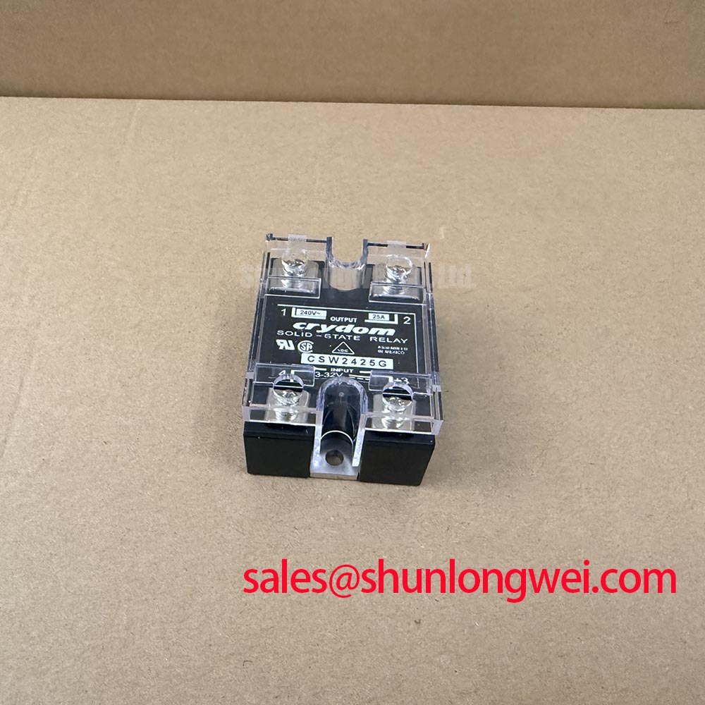
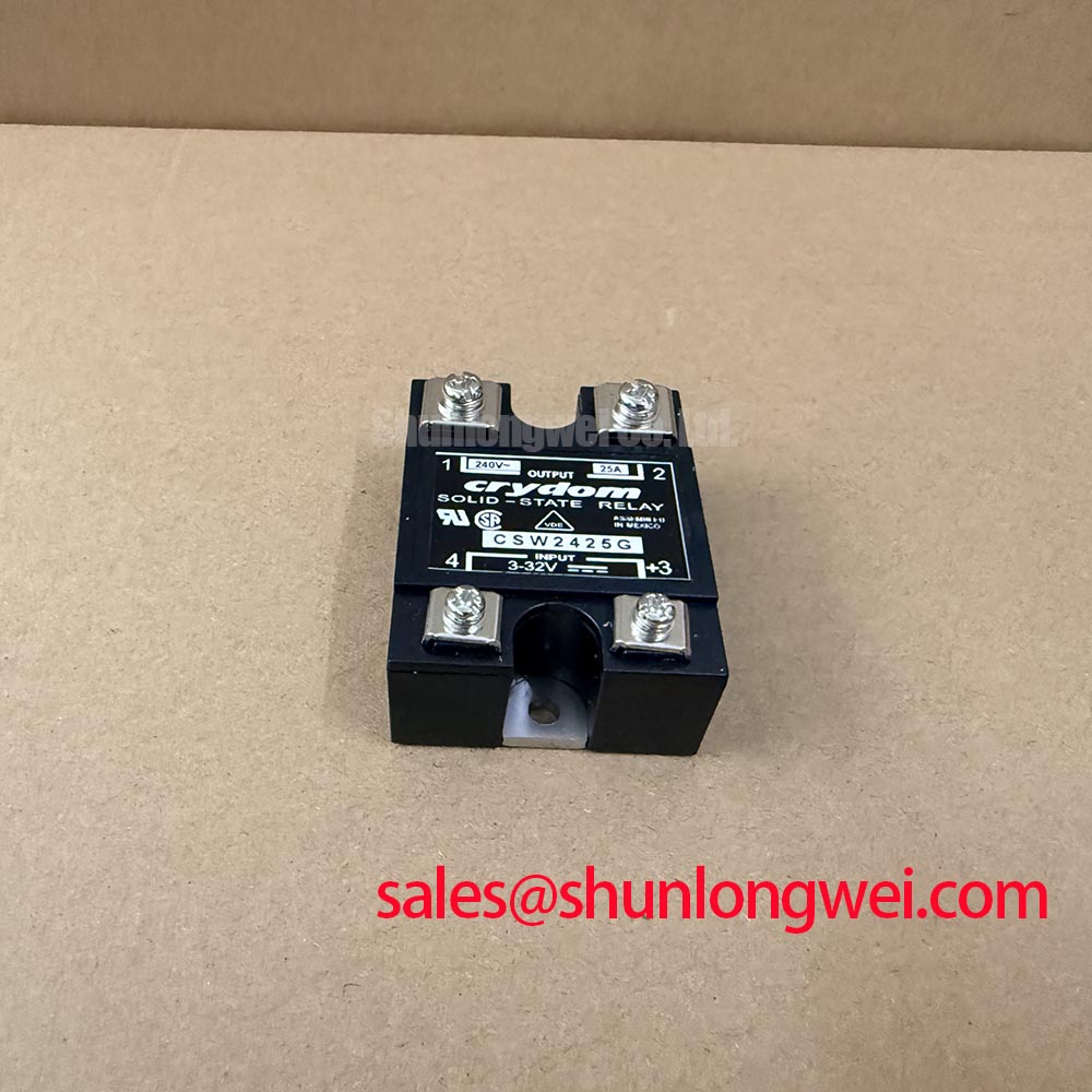
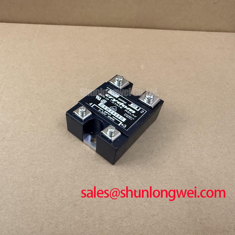
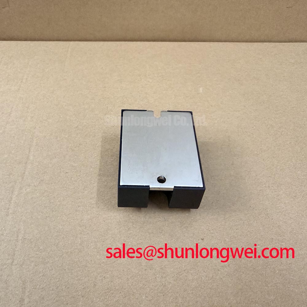
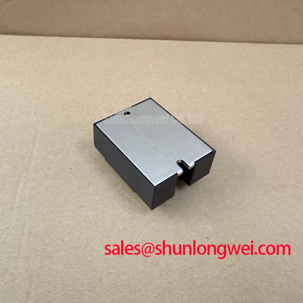
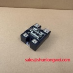
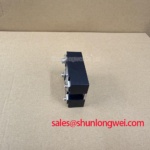
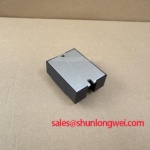
The CSW2425G is a Crydom solid state relay rated at 240 V and 25 A, supplied in a hockey puck panel mount package. Those are official product specifications, not a complete system protection rating. The actual load current, switching frequency, ambient temperature, cooling method, inrush current, and fault-clearing arrangement must be evaluated at equipment level.
Design Consideration: A MOV may be coordinated with the relay and load circuit to absorb transient overvoltage, but its clamping voltage, energy rating, leakage, and failure mode must be selected from the measured DC or AC bus conditions. A semiconductor fuse should be assessed using its published I²t capability against the available fault energy and the relay’s permitted short circuit conditions. Do not infer a safe fault-clearing limit from the 25 A current rating.
Altitude and terrestrial neutron exposure can affect semiconductor reliability, but no FIT, Single Event Burnout, cosmic-ray failure rate, or altitude derating value is established by the supplied CSW2425G data. Treat such analysis as a system reliability study requiring validated manufacturer, IEC, JEDEC, or white-paper data. The JEDEC Global Standards for the Microelectronics Industry provides a useful reference point for qualification and reliability terminology.
For a suspected intermittent actuator shutdown, record the relay input command, load voltage, load current, and thermal condition during a controlled test. A missing output with a valid input may involve the relay, wiring, protection network, or load fault; verify each node rather than assigning a single cause from a static resistance reading.
Thermal Interface and Transient Control for CSW2425G
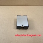
Remove power, release the panel hardware, and inspect the mounting face for uneven contact, contamination, displaced thermal material, and terminal discoloration before reinstalling the relay.
Design Consideration: Thermal interface material should form a continuous, thin, void-free layer suited to the mounting surface. The supplied product information does not specify a required TIM thickness, baseplate flatness, screw torque, or sequential tightening procedure, so these values must come from the original Crydom mechanical documentation and the enclosure design. Tighten fasteners progressively and evenly while preventing the relay body from twisting.
Transient control belongs close to the switching loop. Keep the high-current path compact, reduce unnecessary busbar loop area, and position any snubber film capacitor according to the measured switching waveform. The often-cited inductance targets used in power converters are design objectives, not CSW2425G factory specifications. Confirm overshoot with an appropriately rated differential probe at the relay terminals and load interface.
When this relay is used near a precision stepper or BLDC motor servo actuator, review the motor’s regenerative energy and commutation transients separately from steady-state current. A MOV, RC network, freewheel path, or fuse may each influence stress and EMI, but the correct combination depends on the load topology and switching method. The GD300HFX170C6S can be reviewed as a separate power semiconductor reference, not as a declared drop-in replacement, because no drop-in replacement is specified for this product.
⚠️ Field Alert: Disconnect the control and power wiring before removing the hockey puck relay, and follow the original mounting hardware specification rather than applying a generic torque value.
Field Diagnostics and Control Supply Commissioning
Probe the relay input at the device terminals while the actuator controller commands operation, then check whether the control signal remains within the original system’s documented input limits during startup, stopping, and fault recovery.
The supplied CSW2425G information confirms the solid state relay category and power ratings but does not provide input current, input voltage range, isolation voltage, turn-on delay, turn-off delay, or common-mode transient immunity. Do not apply IGBT gate-driver assumptions, isolated DC-DC sizing rules, or a claimed CMTI threshold to this relay without the relevant datasheet.
Engineering Recommendation: The control supply should be sized for the relay input demand, controller tolerances, wiring losses, and the required isolation architecture. Check for command pulses caused by ground movement, shared returns, contactor noise, or a failing power supply. If an isolated converter is present, verify its reinforced isolation documentation and test the barrier under the equipment’s actual switching conditions.
The CM1000E4C-66R may be examined as a related power-stage device within a broader conversion system, but its electrical characteristics must not be transferred to CSW2425G. For display-equipped service equipment, the MIPI Alliance DSI Display Interface Specification concerns display links and does not define this relay’s control interface.
Operational Boundaries and Busbar Layout Verification
Capture the voltage directly across the relay and load terminals during the fastest switching event, using a probe and bandwidth suitable for the measured transient, then compare the peak with the equipment supply-voltage and protection-device limits.
Switching overshoot is influenced by supply voltage, stray inductance, current slew rate, wiring geometry, and the clamp network. The relationship commonly used for engineering review is that peak voltage rises with the instantaneous supply voltage plus the inductive contribution from loop inductance and current change rate; it is a calculation framework, not a CSW2425G rating. The system designer must verify peak margins during switching tests.
Planar, symmetrical busbar geometry can reduce unequal current paths and magnetic coupling, while short connections between the relay, protection device, and load can help contain parasitic effects. Specific inductance limits, snubber capacitance, clearance distances, and creepage requirements remain system-determined unless stated in the applicable equipment standard and original product documentation.
Use the Power Electronics Masterclass as a broader reference for power-loop inspection and switching reliability. During commissioning, document cold resistance checks, control waveform behaviour, terminal temperature, load current, and transient voltage so future service teams can compare evidence instead of relying on a single symptom.